Inverting Operational Amplifier
An inverting amplifier is one of the most fundamental and widely used configurations of an operational amplifier (op-amp). In this configuration, the input signal is applied to the inverting (−) terminal through a resistor, while the non-inverting (+) terminal is connected to ground. The output signal is a scaled and phase-inverted version of the input.
Basic Concept
The key idea behind the inverting amplifier is the concept of negative feedback. A resistor connects the output back to the inverting input, forcing the op-amp to adjust its output so that the voltage difference between the two input terminals remains extremely small (ideally zero).
Because the non-inverting input is grounded, the inverting input is held at a voltage very close to 0 V. This point is known as a virtual ground. Although it is not physically connected to ground, it behaves as if it were at ground potential.
Circuit Description
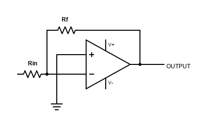
The circuit consists of:
- An input resistor Rin between the signal source and the inverting input
- A feedback resistor Rf between the output and the inverting input
- The non-inverting input connected directly to ground
The input signal current flows through Rin, and because the op-amp input draws almost no current, the same current must flow through Rf. This current relationship is what determines the gain of the amplifier.
Voltage Gain
The voltage gain of an inverting amplifier is given by:
Av = − (Rf / Rin)
The negative sign indicates that the output signal is inverted, meaning it is 180° out of phase with the input. For example:
- If Rf = Rin, the gain is −1 (unity gain, inverted)
- If Rf = 10 × Rin, the gain is −10
Input and Output Behavior
When a positive voltage is applied to the input, current flows into the virtual ground at the inverting input. To maintain equilibrium, the op-amp drives its output negative. Conversely, a negative input voltage results in a positive output voltage.
This inversion property makes the circuit especially useful in signal processing applications where phase reversal or precise gain control is required.
Input Impedance
The input impedance of an inverting amplifier is approximately equal to Rin. This is because the inverting input is held at virtual ground, causing the source to see Rin as the main load.
Unlike the non-inverting amplifier, the input impedance is not extremely high unless Rin itself is chosen to be large.
Advantages
- Simple and predictable gain set by resistor ratio
- Excellent linearity when negative feedback is used
- Easy summing of multiple inputs by adding resistors
- Stable operation with most general-purpose op-amps
Limitations
- Input impedance depends on Rin
- Signal is inverted, which may be undesirable in some applications
- Output swing is limited by the op-amp power supply rails
Typical Applications
Inverting op-amp amplifiers are commonly used in:
- Audio preamplifiers and mixers
- Summing amplifiers
- Active filters
- Signal conditioning circuits
Conclusion
The inverting op-amp amplifier is a cornerstone of analog circuit design. Its predictable behavior, mathematical simplicity, and versatility make it an essential building block in electronics, from audio systems to precision instrumentation.
An inverting amplifier is one of the most fundamental and widely used configurations of an operational amplifier (op-amp). In this configuration, the input signal is applied to the inverting (−) terminal through a resistor, while the non-inverting (+) terminal is connected to ground. The output signal is a scaled and phase-inverted version of the input.
Basic Concept
The key idea behind the inverting amplifier is the concept of negative feedback. A resistor connects the output back to the inverting input, forcing the op-amp to adjust its output so that the voltage difference between the two input terminals remains extremely small (ideally zero).
Because the non-inverting input is grounded, the inverting input is held at a voltage very close to 0 V. This point is known as a virtual ground. Although it is not physically connected to ground, it behaves as if it were at ground potential.
Circuit Description
The circuit consists of:
- An input resistor Rin between the signal source and the inverting input
- A feedback resistor Rf between the output and the inverting input
- The non-inverting input connected directly to ground
The input signal current flows through Rin, and because the op-amp input draws almost no current, the same current must flow through Rf. This current relationship is what determines the gain of the amplifier.
Voltage Gain
The voltage gain of an inverting amplifier is given by:
Av = − (Rf / Rin)
The negative sign indicates that the output signal is inverted, meaning it is 180° out of phase with the input. For example:
- If Rf = Rin, the gain is −1 (unity gain, inverted)
- If Rf = 10 × Rin, the gain is −10
Input and Output Behavior
When a positive voltage is applied to the input, current flows into the virtual ground at the inverting input. To maintain equilibrium, the op-amp drives its output negative. Conversely, a negative input voltage results in a positive output voltage.
This inversion property makes the circuit especially useful in signal processing applications where phase reversal or precise gain control is required.
Input Impedance
The input impedance of an inverting amplifier is approximately equal to Rin. This is because the inverting input is held at virtual ground, causing the source to see Rin as the main load.
Unlike the non-inverting amplifier, the input impedance is not extremely high unless Rin itself is chosen to be large.
Advantages
- Simple and predictable gain set by resistor ratio
- Excellent linearity when negative feedback is used
- Easy summing of multiple inputs by adding resistors
- Stable operation with most general-purpose op-amps
Limitations
- Input impedance depends on Rin
- Signal is inverted, which may be undesirable in some applications
- Output swing is limited by the op-amp power supply rails
Typical Applications
Inverting op-amp amplifiers are commonly used in:
- Audio preamplifiers and mixers
- Summing amplifiers
- Active filters
- Signal conditioning circuits
Conclusion
The inverting op-amp amplifier is a cornerstone of analog circuit design. Its predictable behavior, mathematical simplicity, and versatility make it an essential building block in electronics, from audio systems to precision instrumentation.