Non-Inverting Operational Amplifier
A non-inverting op-amp amplifier is one of the most commonly used operational-amplifier configurations. In this arrangement, the input signal is applied to the non-inverting (+) terminal, while the inverting (−) terminal is connected to a feedback network made of resistors. As the name suggests, the output signal is in phase with the input (no polarity reversal).
Basic Configuration
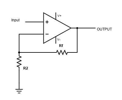
In a non-inverting amplifier, the input voltage Vin is directly connected to the (+) input of the op-amp. The (−) input receives a fraction of the output voltage through a resistive voltage divider formed by two resistors:
- R1: connected between the inverting input and ground
- R2: connected between the output and the inverting input
This negative feedback forces the op-amp to adjust its output so that the voltage at the inverting input matches the voltage at the non-inverting input.
Voltage Gain
The closed-loop voltage gain of a non-inverting amplifier depends only on the resistor values and is given by:
Av = 1 + (R2 / R1)
Key observations:
- The gain is always greater than or equal to 1
- If R2 = 0, the circuit becomes a voltage follower (buffer)
- The gain is positive, so the output is in phase with the input
Phase Relationship
Unlike the inverting amplifier, the non-inverting configuration does not invert the signal. A positive change in the input voltage causes a positive change at the output. This makes it very useful in applications where signal polarity must be preserved, such as sensor conditioning and audio preamplifiers.
Input Impedance
One major advantage of the non-inverting amplifier is its very high input impedance. Since the input is applied directly to the op-amp’s non-inverting terminal, almost no current is drawn from the signal source.
This makes the non-inverting configuration ideal for:
- Interfacing with high-impedance sensors
- Audio sources that should not be loaded
- Buffering weak or sensitive signals
Output Impedance
Due to negative feedback, the output impedance of a non-inverting amplifier is very low. This allows the amplifier to drive loads effectively without significant voltage drop, as long as the load current is within the op-amp’s limits.
Voltage Follower (Unity Gain Buffer)
When the output is directly connected to the inverting input and R1 is removed, the gain becomes:
Av = 1
This configuration is known as a voltage follower. It provides no voltage amplification but offers excellent buffering by combining very high input impedance with very low output impedance.
Practical Considerations
In real-world circuits, several practical limitations must be considered:
- The output voltage cannot exceed the op-amp’s supply rails
- The gain is limited by the op-amp’s bandwidth (gain-bandwidth product)
- Input common-mode voltage range must include the input signal
- Noise and offset voltages may be amplified along with the signal
Typical Applications
- Audio preamplifiers
- Sensor signal conditioning
- Voltage buffers
- Instrumentation and measurement circuits
Summary
The non-inverting op-amp amplifier is a simple, stable, and versatile configuration. Its high input impedance, predictable gain, and in-phase output make it a preferred choice in many analog signal-processing applications, especially where signal integrity must be preserved.