
Build an Audio Delay & Echo Processor
An audio delay processor stores an audio signal for a short period and then mixes the delayed signal with the original. By controlling the delay time, feedback and mix level, the circuit can produce effects ranging from a subtle doubling effect to a clearly audible echo.
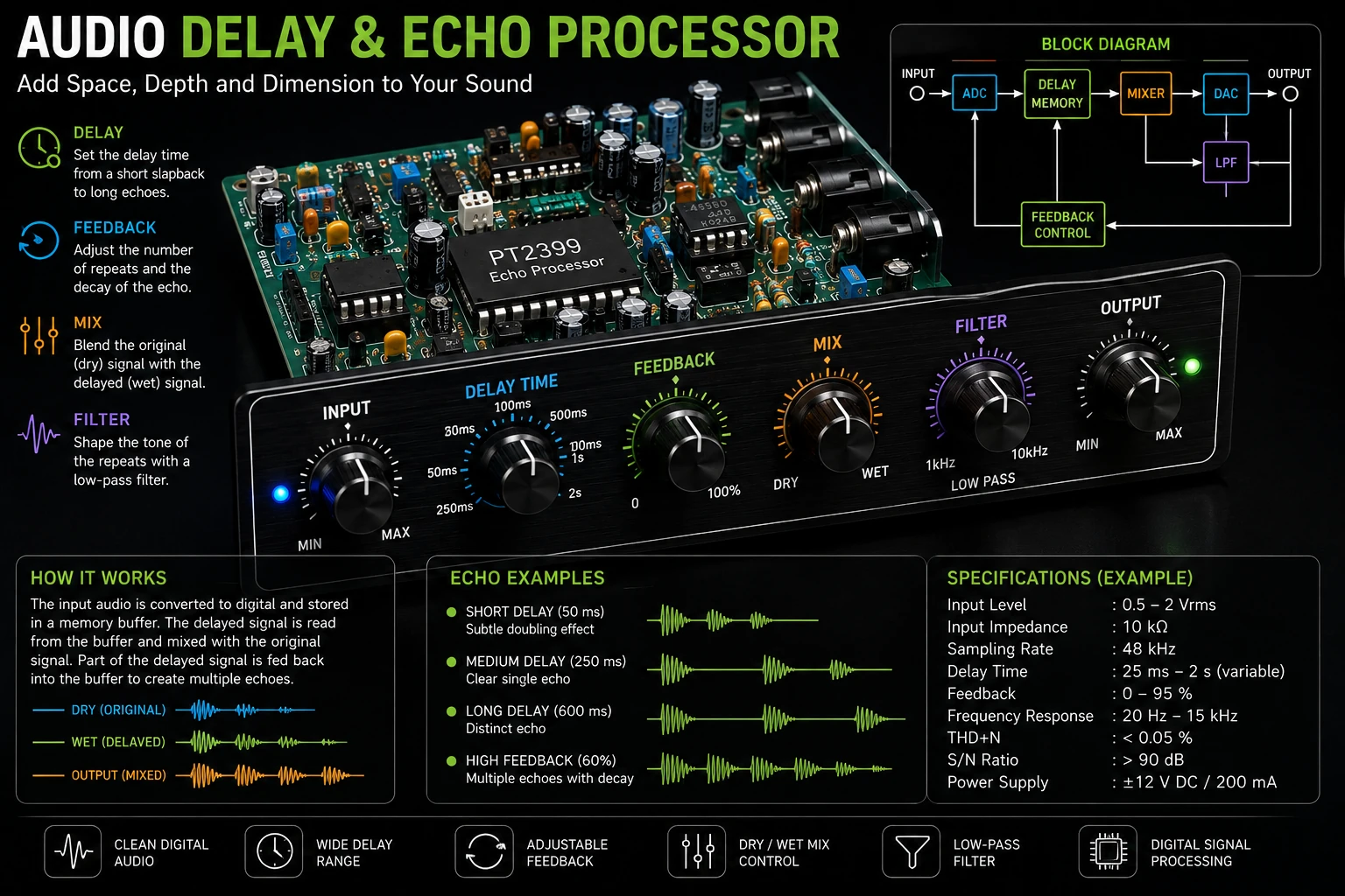
Project Overview
A delay effect is created by reproducing an audio signal after a controlled time interval.
Audio Input
     │
     ├──────────────────────┐
     │                      │
     ▼                      │
 Delay Line                 │
     │                      │
     ▼                      │
Delayed Signal              │
     │                      │
     └──────────┬───────────┘
                ▼
              Mixer
                │
                ▼
           Audio Output
The original signal remains audible while a delayed copy is added to the output.
What Creates an Echo?
When a delayed copy of a sound is played after the original, the listener perceives a separate repetition of the sound.
For example, with a delay of 500 milliseconds:
Original ───────────────►

Delayed ────────────────►
          500 ms later
Increasing the delay makes the repetitions more clearly separated.
Delay Time
The delay time determines how long the processor waits before reproducing the stored signal.
| Delay Time | Typical Effect |
|---|---|
| 1–20 ms | Very short doubling / coloration |
| 20–80 ms | Doubling and chorus-like effects |
| 80–200 ms | Slapback-style effect |
| 200–600 ms | Distinct echo |
| 600 ms and above | Long echo repetitions |
Analog Delay
Older audio delay effects used analog delay-line devices to store the audio signal temporarily.
Bucket-brigade devices are an example of this approach.
Audio Input
    │
    ▼
Input Filter
    │
    ▼
BBD Delay Line
    │
    ▼
Output Filter
    │
    ▼
Audio Output
The signal is transferred through a chain of storage stages according to the clock frequency.
Bucket-Brigade Delay
A bucket-brigade device can be thought of as a chain of small storage elements that pass the sampled analog signal from one stage to the next.
The clock determines how quickly the signal moves through the device.
More stages generally provide a longer delay for a given clock frequency.
Because the signal remains analog, suitable filtering is required to control clock noise and aliasing-related artifacts.
Digital Delay
Modern delay processors usually store the audio signal digitally.
Audio Input
     │
     ▼
ADC
     │
     ▼
Digital Memory
     │
     ▼
DAC
     │
     ▼
Audio Output
The delay time can be controlled by determining which previously stored samples are read from memory.
Sample-Based Delay
In a digital system, delay time depends on the sampling rate and the number of samples between writing and reading the signal.
Delay Samples = Delay Time × Sampling Rate
For example, at a 48 kHz sampling rate, a 100 ms delay requires:
0.1 × 48000 = 4800 samples
The processor therefore needs to maintain the appropriate distance between the input write position and output read position.
Circular Buffer
A circular buffer is a convenient way to implement a digital audio delay.
Memory

[0] [1] [2] [3] [4] [5] [6] [7]
 ↑                         ↑
Write                     Read

After reaching the end,
the pointer returns to [0].
The write pointer continuously stores new samples while the read pointer retrieves samples from an earlier position.
Mixing the Delayed Signal
The dry, or original, signal can be mixed with the delayed signal.
Dry Signal ───────────────┐
                          ▼
                        Mixer
                          ▲
                          │
Delayed Signal ───────────┘
                          │
                          ▼
                     Audio Output
The balance between the two signals determines how prominent the echo sounds.
Feedback
Feedback sends part of the delayed signal back into the delay line.
             ┌────────────────────┐
             │                    │
             ▼                    │
Input ───► Delay ───► Output      │
             ▲                    │
             │                    │
             └──── Feedback ──────┘
Without feedback, there is normally one delayed repetition.
With feedback, the delayed signal is repeatedly fed back through the delay line, producing multiple echoes.
Feedback Level
The feedback level determines how quickly the repeated echoes decay.
Low feedback produces only a few repetitions.
Higher feedback produces more repetitions and a longer decay.
The feedback system must remain below the point where the loop becomes unstable.
Echo Block Diagram
                 ┌───────────────────────┐
                 │                       │
                 │      Feedback         │
                 │                       │
                 ▼                       │
Audio ───► Delay Line ───► Level ────────┘
  │                         │
  │                         │
  └──────────────► Dry ─────┤
                            ▼
                           Mixer
                            │
                            ▼
                         Output
Low-Pass Filtering
Repeated digital or analog delay processing can introduce high-frequency artifacts.
A low-pass filter can be placed in the feedback path so that each successive echo contains progressively less high-frequency content.
Delay │ ▼ Low-Pass Filter │ ▼ FeedbackThis can produce a more natural-sounding echo.
Digital Audio Processing
A microcontroller or digital signal processor can perform the complete delay operation.
Audio ADC │ ▼ Microcontroller / DSP │ ├── Delay Buffer ├── Feedback ├── Mix └── Filtering │ ▼ Audio DAC │ ▼ Audio Amplifier
The processor must have enough memory and processing performance for the selected sampling rate, delay time and audio resolution.
Memory Requirements
The required memory increases with delay time and sampling rate.
Memory ≈ Samples × Bytes per Sample × Channels
For stereo audio, the memory requirement is approximately twice that of a single-channel implementation using the same sample format.
Interpolation
If the desired delay time does not correspond exactly to an integer number of samples, interpolation can be used.
This allows smoother and more precise delay-time adjustment.
Interpolation becomes particularly useful when the delay time is continuously changed while audio is playing.
Variable Delay
Changing the delay time while audio is being processed can produce pitch-shifting effects.
If the read position moves relative to the write position, the rate at which stored samples are reproduced changes.
This principle is used in effects such as chorus, flanging and certain pitch-shifting systems.
Chorus and Flanging
Very short delays combined with modulation can create chorus and flanging effects.
LFO │ ▼ Delay Time │ ▼ Variable Delay │ ▼ Mixer
A low-frequency oscillator can continuously vary the delay time.
Stereo Delay
A stereo processor can use different delay times for the left and right channels.
Left ─► Delay A ─► Left Output Right ─► Delay B ─► Right Output
Small differences between the channels can create a wider spatial effect.
Ping-Pong Delay
A ping-pong delay alternates echoes between the left and right channels.
Left Input │ ▼ Delay │ ▼ Right │ ▼ Delay │ ▼ Left
This creates a pronounced stereo movement.
Audio Level Control
The input and output levels should be controlled carefully to prevent clipping.
An input buffer and level-control stage can be used before the delay processor.
Audio Input │ ▼ Buffer │ ▼ Level Control │ ▼ Delay Processor
Avoiding Clipping
If the dry signal and delayed signal are simply added together, the combined signal can exceed the available signal range.
The mixer should therefore provide appropriate gain control or scaling.
This is particularly important when feedback is enabled.
Controls
A practical delay processor can provide controls for:
- Delay time.
- Feedback.
- Dry level.
- Wet level.
- Input level.
- Output level.
- Filter cutoff.
Testing the Delay
A short impulse or percussion sound is useful when testing an echo processor.
The original sound should be heard first, followed by the delayed repetition.
Increase the delay time and verify that the separation between the original and delayed sound increases.
Testing Feedback
Start with feedback at a low setting.
Gradually increase the feedback and listen to the number and decay of the repetitions.
Do not allow the feedback loop to become unstable.
Troubleshooting
No Delay Effect
- Check the delay buffer.
- Check the read and write positions.
- Check the wet signal level.
- Check the audio routing.
- Check the delay-time setting.
Distorted Audio
- Reduce the input level.
- Check for digital clipping.
- Reduce feedback.
- Check ADC and DAC levels.
- Check the output mixer gain.
Noisy Echo
- Check the power supply.
- Check grounding.
- Check the ADC and DAC filtering.
- Check analog signal levels.
- Reduce unnecessary high-frequency noise.
Unstable Feedback
- Reduce feedback level.
- Check mixer gain.
- Check filtering.
- Check for unintended positive feedback paths.
Common Applications
- Vocal echo effects.
- Guitar effects.
- Keyboard effects.
- Studio processors.
- PA systems.
- Karaoke equipment.
- Music production.
- Digital audio experiments.
Safety Notes
- Use a suitable low-voltage supply for the processor.
- Do not connect speaker-level signals directly to low-level inputs.
- Use suitable attenuation when measuring amplifier outputs.
- Disconnect equipment before modifying wiring.
- Use appropriate isolation when working with mains-powered audio equipment.
Skills Learned
- Audio signal processing.
- Delay lines.
- Digital audio memory.
- Circular buffers.
- Feedback systems.
- Audio mixing.
- Digital filtering.
- ADC and DAC operation.
- Stereo processing.
- Audio effects design.
Key Points
- A delay processor reproduces an audio signal after a controlled time interval.
- Feedback creates repeated echoes.
- Dry and delayed signals can be mixed to control the effect depth.
- Digital delay can use a circular memory buffer.
- Delay time depends on sampling rate and stored samples.
- Filtering can make repeated echoes sound more natural.
- Very short modulated delays can produce chorus and flanging.
- Stereo delay can create wider spatial effects.
- Input and output levels must be controlled to prevent clipping.