
Build an Automatic Battery Cooling System
An automatic battery cooling system monitors battery temperature and activates a cooling fan when the temperature becomes too high. This project combines temperature sensing, microcontroller control, hysteresis and fan switching to help maintain a suitable operating temperature for batteries and battery-powered equipment.
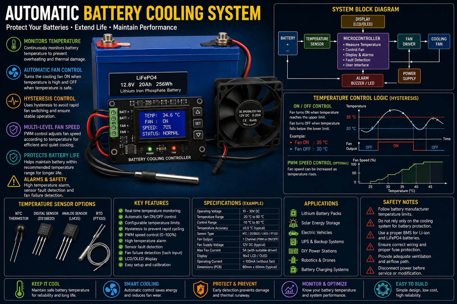
Project Overview
Battery temperature can increase during charging, discharging or high-current operation. A temperature-controlled fan can automatically remove excess heat when cooling is required.
Battery
   │
   ▼
Temperature Sensor
   │
   ▼
Microcontroller
   │
   ├────► Temperature Display
   │
   ▼
Control Logic
   │
   ▼
Fan Driver
   │
   ▼
Cooling Fan
The controller continuously monitors the battery temperature and controls the fan according to programmed temperature limits.
Why Battery Cooling Is Important
Excessive temperature can reduce battery performance and may accelerate battery ageing. The acceptable operating temperature depends on the battery chemistry and the manufacturer's specifications.
Cooling should therefore be designed around the actual battery type and its intended operating conditions.
Temperature Sensor
The sensor should be mounted where it can accurately represent the battery temperature.
Possible sensors include:
- NTC thermistors.
- Analog temperature sensors.
- Digital temperature sensors.
- RTDs.
A digital sensor can simplify the measurement circuit because the temperature conversion is performed by the sensor itself.
Sensor Placement
Sensor placement is important because the temperature measured by the sensor may not represent the actual battery temperature if the sensor is poorly positioned.
- Place the sensor close to the battery surface.
- Provide good thermal contact where appropriate.
- Keep the sensor away from the fan airflow if possible.
- Protect the sensor from mechanical damage.
- Protect the sensor connection from vibration and moisture.
Basic Control System
Measure Temperature
        │
        ▼
Compare With Limit
        │
        ▼
Fan Control
        │
        ▼
Cool Battery
        │
        ▼
Measure Again
The controller repeats this process continuously.
Fan ON Temperature
The fan should start when the battery temperature reaches a selected upper threshold.
For example:
Fan ON = 35 °C
The actual temperature should be selected according to the battery manufacturer's recommended operating range.
Hysteresis
Hysteresis prevents the fan from repeatedly switching on and off when the temperature is close to the control threshold.
For example:
Fan ON  = 35 °C
Fan OFF = 30 °C
The fan remains on while the battery cools from 35 °C toward 30 °C.
Why Hysteresis Matters
Without hysteresis, the controller could behave like this:
35.0 °C → FAN ON
34.9 °C → FAN OFF
35.0 °C → FAN ON
34.9 °C → FAN OFF
This rapid switching increases relay or transistor activity and can reduce fan life.
A temperature dead band provides much more stable operation.
DC Fan Control
A low-voltage DC fan can be controlled using a transistor or MOSFET.
Microcontroller
      │
      ▼
Gate / Base Driver
      │
      ▼
MOSFET / Transistor
      │
      ▼
Cooling Fan


The switching device should be selected according to the fan voltage
and current.
MOSFET Fan Driver
A logic-level MOSFET can be used to switch a DC fan when its gate can be fully driven by the controller.
+V │ ▼ FAN │ ▼ Drain MOSFET Source │ ▼ GND ```A suitable gate resistor and pull-down or pull-up arrangement can be used according to the circuit design.
Fan Flyback Protection
A DC fan contains an inductive motor winding and can generate voltage transients when switched off.
A suitable suppression device can reduce switching transients and protect the driver circuit.
Some brushless DC fans contain internal electronics, so the protection requirements should be considered according to the actual fan.
PWM Fan Control
Instead of simply switching the fan fully ON or OFF, PWM can be used to control its average power.
Temperature Low │ ▼ Low Fan Speed Temperature Higher │ ▼ Higher Fan Speed Temperature Very High │ ▼ Maximum Fan Speed
This can reduce noise and power consumption when full cooling capacity is not required.
Temperature-Based Fan Speed
A simple multi-level control scheme could be:
Below 30 °C Fan OFF 30–35 °C Low Speed 35–40 °C Medium Speed Above 40 °C High Speed
These values are only examples. The actual limits should be selected according to the battery manufacturer's specifications.
Microcontroller
An ESP32, Arduino-compatible microcontroller or another suitable controller can perform the temperature measurement and fan control.
The controller can also provide:
- Temperature display.
- Fan status.
- Temperature alarms.
- Data logging.
- Fault detection.
- Communication.
Temperature Display
A small LCD or OLED can display the current battery temperature and cooling status.
┌────────────────────────┐ │ BATTERY TEMP: 34.6 °C │ │ FAN: ON │ │ SPEED: 60 % │ │ STATUS: NORMAL │ └────────────────────────┘
High-Temperature Alarm
The system can include an alarm threshold above the normal cooling range.
Temperature │ ▼ High Limit │ ├────► Buzzer │ ├────► Display Warning │ └────► Maximum Cooling
The alarm should not be treated as a replacement for the battery manufacturer's safety systems.
Emergency Shutdown
If the temperature reaches a dangerous level, the controller can disable charging or discharging equipment when the overall system design permits it.
Critical battery protection should not depend exclusively on a hobby microcontroller. Appropriate battery-management and protection hardware should be used where required.
Charging and Cooling
Battery temperature can rise during charging, particularly at higher charge currents.
The cooling controller can monitor the temperature during charging and activate the fan when necessary.
The battery charger itself should still provide the correct charging control and temperature protection for the battery chemistry.
Discharging and Cooling
High-current discharge can also produce heat.
The cooling system can monitor the battery while the load is operating and increase cooling when the temperature rises.
Battery Chemistry
Different battery chemistries have different temperature limits and thermal characteristics.
The controller should therefore not use arbitrary temperature limits for every battery.
Examples include:
- Lead-acid batteries.
- Nickel-metal hydride batteries.
- Lithium-ion batteries.
- LiFePO4 batteries.
Always follow the battery manufacturer's specifications.
Temperature Averaging
Temperature readings can fluctuate because of sensor noise and small changes in thermal conditions.
Software averaging can provide a more stable reading.
Average = (T1 + T2 + T3 + T4) / 4
The averaging period should remain short enough to allow the controller to respond appropriately to rapid temperature changes.
Sensor Fault Detection
The controller should detect abnormal sensor readings.
For example, a disconnected sensor may produce a reading outside the expected temperature range.
Invalid Sensor │ ▼ Sensor Fault │ ├────► Alarm │ └────► Safe Output State
A failed temperature sensor should not cause the system to assume that the battery is safely cool.
Fan Failure Detection
A temperature controller can also monitor whether the cooling fan is actually operating.
Fans with a tachometer output can provide speed feedback to the controller.
Fan │ ├── Power │ └── Tachometer │ ▼ Microcontroller
If the fan is commanded ON but its speed remains zero, the controller can generate a fault indication.
Airflow
The fan should be positioned so that air flows effectively across the battery or through the battery enclosure.
The cooling system should provide an intentional airflow path rather than simply placing a fan near the battery.
- Provide an air inlet.
- Provide an air outlet.
- Avoid blocked vents.
- Use suitable fan capacity.
- Keep the airflow path as short as practical.
Dust and Moisture
Fans can draw dust into an enclosure.
Depending on the environment, filters or suitable enclosure protection may be required.
Moisture protection is also important when the battery system is used in damp environments.
Power Supply
The cooling controller and fan require a suitable power source.
The fan startup current should be considered when selecting the power supply and switching device.
The controller supply should remain stable when the fan starts.
PCB Layout
The fan current should be kept away from sensitive temperature-sensor signals.
- Use suitable trace widths for fan current.
- Place sensor circuitry away from switching noise.
- Provide local controller decoupling.
- Keep sensor wiring short where possible.
- Separate high-current and low-level signal paths.
Testing the Cooling System
- Inspect the PCB.
- Verify the sensor connection.
- Verify the controller supply.
- Check the displayed temperature.
- Test the fan driver.
- Verify the fan direction and airflow.
- Test the fan ON threshold.
- Test the fan OFF threshold.
- Test the high-temperature alarm.
- Test sensor-failure detection.
- Test fan-failure detection if available.
- Monitor battery temperature under controlled load conditions.
Troubleshooting
Fan Does Not Start
- Check the temperature threshold.
- Check the sensor reading.
- Check the MOSFET or transistor.
- Check the fan supply voltage.
- Check the fan wiring.
Fan Runs Continuously
- Check the temperature sensor.
- Check the programmed threshold.
- Check hysteresis settings.
- Check for excessive battery temperature.
- Check the output transistor.
Temperature Reading Is Incorrect
- Check sensor placement.
- Check sensor calibration.
- Check sensor wiring.
- Check the controller reference voltage.
- Check the sensor type in firmware.
Controller Resets When Fan Starts
- Check the power supply.
- Check fan startup current.
- Improve supply decoupling.
- Separate fan current from controller supply wiring.
- Check the switching transistor.
Battery Remains Too Hot
- Check fan airflow.
- Check fan capacity.
- Check enclosure ventilation.
- Check sensor placement.
- Check the battery load current.
- Check the cooling threshold.
Common Mistakes
- Using arbitrary temperature limits.
- Placing the sensor away from the battery.
- Using an undersized fan.
- Ignoring fan startup current.
- Failing to provide hysteresis.
- Relying only on software for critical battery protection.
- Ignoring airflow direction.
- Failing to detect sensor faults.
- Allowing dust to block the cooling system.
Applications
- Battery packs.
- Solar energy storage systems.
- Electric vehicle battery systems.
- Workshop battery systems.
- High-current power supplies.
- Portable power stations.
- Battery charging systems.
- Electronics enclosures.
Safety Notes
- Use temperature limits appropriate for the actual battery chemistry.
- Do not rely on the cooling fan as the only battery protection system.
- Use a proper battery-management system where required.
- Do not operate damaged, swollen or leaking batteries.
- Protect the battery against over-current and over-temperature conditions.
- Use appropriately rated wiring and connectors.
- Keep ventilation openings clear.
- Disconnect power before servicing the cooling circuit.
Skills Learned
- Temperature measurement.
- Thermal control.
- Hysteresis.
- Fan switching.
- MOSFET control.
- PWM fan control.
- Sensor fault detection.
- Temperature alarms.
- Thermal management.
- Automatic cooling systems.
Key Points
- Battery temperature should be monitored according to the battery manufacturer's requirements.
- A temperature sensor provides the feedback required for automatic cooling.
- Hysteresis prevents rapid fan switching.
- A MOSFET can efficiently control a DC cooling fan.
- PWM can provide variable fan speed.
- Sensor-failure detection improves system safety.
- Fan-failure detection can provide an additional layer of protection.
- Good airflow is as important as selecting an appropriate fan.
- Battery cooling should complement, not replace, proper battery-management protection.
- Different battery chemistries require different thermal limits.