Clip LED Indicator
This circuit rectifies the audio, holds the peak briefly, and compares it to a set threshold to drive an LED right at the onset of clipping.
Schematic
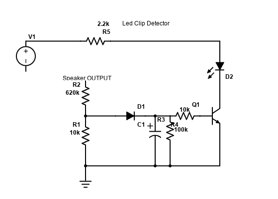
See clip-led-indicator.png. Typical blocks: precision rectifier (op-amp + diodes), peak-hold (R-C), comparator/transistor to drive LED.
Parts list
| Item | Spec / Notes |
|---|---|
| Op-amp | LM358/TL072 (rail choice depends on supply) |
| Diodes | 1N4148 (rectifier) |
| R-C peak | 100 k + 1 µF (≈100 ms hold) |
| Comparator | LM393 / use op-amp as comparator |
| LED + R | e.g., 2 k2 with red LED @ 24 V line; adjust as needed |
| Supply | Same as preamp rails (±15 V) or single 12–24 V with bias |
How it works
- Rectify & peak: Precision rectifier avoids diode drop error; RC holds peaks so the LED is visible.
- Threshold: Set the comparator reference to your desired clip point (e.g., 1 dB below amp’s max).
- Drive: Transistor or op-amp output sinks LED current; add series resistor for LED.
Tip: Set threshold using a known sine level at the point your power amp just starts to flatten on a scope.
Build & calibration
- Assemble the rectifier and peak network close to the comparator to reduce noise.
- Feed a 1 kHz sine and increase level until the power amp begins clipping.
- Adjust the threshold trimmer so the LED turns on right at that point.