
Build a Digital Ammeter
A digital ammeter measures electrical current and displays the result as a numerical value. This project demonstrates how a precision shunt resistor, voltage measurement circuit, ADC and microcontroller can be combined to create a practical digital current meter.
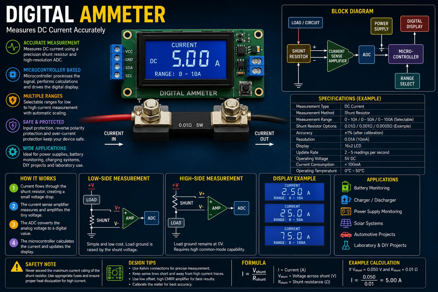
Project Overview
Current cannot normally be connected directly to a voltage-measuring input. Instead, the current is passed through a carefully selected low-value resistor called a shunt resistor.
The small voltage developed across the shunt is measured and converted into current.
Load Current
     │
     ▼
Shunt Resistor
     │
     ▼
Small Voltage
     │
     ▼
Amplifier / ADC
     │
     ▼
Microcontroller
     │
     ▼
Digital Display
Ohm's Law
The basic principle of a shunt ammeter comes from Ohm's law:
V = I × R
Therefore:
I = V / R
If the resistance of the shunt is known, measuring the voltage across it allows the current to be calculated.
Shunt Resistor
The shunt resistor is normally a very low resistance value so that the voltage drop and power loss remain small.
For example, with a 0.01 Ω shunt and 5 A flowing through it:
V = 5 × 0.01

V = 0.05 V

V = 50 mV
The measuring circuit therefore needs to accurately measure a relatively small voltage.
Shunt Power Dissipation
The power dissipated by the shunt is:
P = I² × R
For a 0.01 Ω shunt carrying 5 A:
P = 5² × 0.01

P = 0.25 W
The shunt should have an appropriate power rating with suitable thermal margin.
Shunt Selection
The shunt resistance is a compromise between measurement sensitivity and power loss.
A larger resistance produces a larger measurement voltage but also causes a larger voltage drop and greater power dissipation.
Important specifications include:
- Resistance value.
- Maximum current.
- Power rating.
- Temperature coefficient.
- Accuracy.
- Long-term stability.
Low-Side Current Measurement
The simplest arrangement places the shunt between the load and ground.
Supply
  │
  ▼
 Load
  │
  ▼
 Shunt
  │
  ▼
 GND
The voltage across the shunt can then be amplified and measured by an ADC.
The disadvantage is that the load ground is raised slightly above the system ground by the shunt voltage.
High-Side Current Measurement
A high-side ammeter places the shunt between the supply and the load.
Supply
  │
  ▼
 Shunt
  │
  ▼
 Load
  │
  ▼
 GND
High-side measurement keeps the load ground close to the system ground but requires a measurement circuit capable of handling the common-mode voltage.
Current-Sense Amplifier
A current-sense amplifier can measure the small differential voltage across the shunt and provide a larger voltage suitable for an ADC.
Shunt
 │ │
 │ └──────────────┐
 │                │
 ▼                ▼
Current-Sense Amplifier
         │
         ▼
        ADC
Dedicated current-sense amplifiers can provide accurate differential measurement while rejecting the common voltage present at the shunt.
Differential Measurement
The voltage of interest is the difference between the two sides of the shunt.
Vshunt = V+ - V-
A differential amplifier or instrumentation amplifier can measure this difference.
Careful PCB layout is important because the measured voltage may only be a few millivolts.
ADC Measurement
A microcontroller ADC converts the amplified shunt voltage into a digital number.
Current
  │
  ▼
Shunt
  │
  ▼
Amplifier
  │
  ▼
ADC
  │
  ▼
Microcontroller
  │
  ▼
Display
The ADC resolution determines how finely the voltage can be measured.
ADC Resolution
For an ideal N-bit ADC with a reference voltage of Vref:
ADC Step = Vref / (2^N)
For example, a 12-bit ADC has:
2^12 = 4096 levels
A lower ADC reference voltage can improve resolution when the signal range is small, provided the ADC and reference remain within their specified operating conditions.
Scaling the Measurement
Suppose a shunt produces 50 mV at maximum current and an amplifier provides a gain of 20.
VADC = 0.05 × 20

VADC = 1.0 V
The ADC can then measure a much larger and easier-to-resolve voltage.
Current Calculation
The microcontroller can calculate current from the measured ADC voltage.
If the amplifier gain is G:
I = VADC / (G × Rshunt)
The software can then convert the result into amperes and display it.
Digital Display
The measured current can be displayed using several types of display.
- LCD.
- OLED.
- Seven-segment display.
- TFT display.
- LED numerical display.
The display resolution should be appropriate for the measurement range.
Multiple Current Ranges
A practical ammeter can provide several current ranges.
Different shunts can be selected using relays, MOSFETs or analog switches.
Input
 │
 ├── Shunt 1 ── Low Current Range
 │
 ├── Shunt 2 ── Medium Range
 │
 └── Shunt 3 ── High Current Range
The selected shunt determines the maximum measurable current and measurement sensitivity.
Automatic Range Selection
An automatic-ranging ammeter can select an appropriate measurement range according to the measured current.
The controller should change ranges carefully so that the switching circuit does not interrupt or excessively disturb the load current.
Kelvin Connections
Precision current measurement benefits from four-terminal Kelvin connections.
Power Current
──────────────►
   │
   ├──── Shunt ────┤
   │               │
   └── Sense ──────┘
The heavy current connections carry the load current while separate sense connections measure only the voltage across the shunt.
This prevents voltage drops in PCB traces and connectors from becoming part of the measurement.
Calibration
The completed ammeter should be calibrated against a known current.
A controlled load can be used to establish one or more calibration points.
Reference Ammeter
       │
       ▼
Known Load
       │
       ▼
Device Under Test
The measured value can then be compared with the reference instrument.
Zero Offset
The amplifier and ADC may produce a small reading even when no current is flowing.
This is called zero offset.
The controller can measure the zero-current condition and subtract the offset from subsequent measurements.
Temperature Effects
Shunt resistance changes with temperature.
The amplifier and reference voltage can also have temperature coefficients.
For precision applications, the temperature characteristics of the complete measurement chain should be considered.
Filtering
Electrical loads can produce rapidly changing currents.
The measured signal can therefore contain switching noise and ripple.
A small analog filter or digital averaging algorithm can reduce unwanted fluctuations.
Shunt
 │
 ▼
Amplifier
 │
 ▼
Low-Pass Filter
 │
 ▼
ADC
 │
 ▼
Digital Average
 │
 ▼
Display
Filtering should not be excessive because it can make the displayed value respond too slowly to genuine current changes.
Sampling Rate
The ADC sampling rate determines how frequently the current is measured.
A higher rate is useful when monitoring rapidly changing loads.
For a slowly changing DC supply, a lower sampling rate combined with averaging may be sufficient.
Peak Current Measurement
If the load contains motors, switching converters or other dynamic circuits, the peak current may be substantially higher than the average current.
The software can maintain separate average and peak measurements.
Current

Peak ────────┐
             │
      /\     │
     /  \    │
────/────\───┴────────
       Time
Current Direction
A basic shunt ammeter measures current in one direction.
Bidirectional current measurement requires a suitable differential measurement circuit and a reference point around which positive and negative currents can be detected.
This is useful in battery charging and discharging applications.
Power Measurement
Once current and voltage are known, electrical power can be calculated.
P = V × I
A digital instrument can therefore be expanded into a power meter.
Voltage Measurement ──┐
                      ├──► Microcontroller ──► Display
Current Measurement ──┘
Energy Measurement
Electrical energy can be calculated by integrating power over time.
Energy = ∫ P dt
For a constant load, the relationship can be simplified to:
Energy = Power × Time
This allows the instrument to display watt-hours in addition to current.
Protection
The shunt and measurement circuit should be protected against currents above the intended measurement range.
- Input fuse.
- Current limiting.
- Transient protection where appropriate.
- Over-voltage protection for the ADC input.
- Thermal protection for high-current shunts.
Shunt Overload
A current significantly above the rated value can cause the shunt to overheat.
The shunt should therefore be selected with appropriate power and pulse-current margins.
A fuse can provide an additional layer of protection against severe over-current conditions.
PCB Layout
The measurement circuit can be affected by voltage drops and switching noise on the PCB.
- Use Kelvin connections for precision shunts.
- Keep sense traces away from high-current switching paths.
- Use a clean analog ground.
- Keep ADC reference wiring short.
- Place filtering close to the ADC input.
- Use suitable copper widths for high-current paths.
Testing the Ammeter
- Inspect the PCB.
- Verify the shunt resistance.
- Check the amplifier supply.
- Verify the ADC reference.
- Power the instrument without load current.
- Check the zero reading.
- Apply a small known current.
- Compare the reading with a reference meter.
- Increase the current gradually.
- Check shunt temperature.
- Verify the maximum measurement range.
Troubleshooting
Reading Is Always Zero
- Check the shunt connections.
- Check the amplifier supply.
- Check the ADC input.
- Check the software scaling.
- Check the current path through the shunt.
Reading Is Too High
- Check the shunt resistance value.
- Check amplifier gain.
- Check ADC reference voltage.
- Check calibration constants.
- Check PCB trace voltage drops.
Reading Is Unstable
- Check grounding.
- Check power-supply noise.
- Improve filtering.
- Check ADC reference stability.
- Check sense-trace routing.
Shunt Gets Hot
- Check current.
- Check shunt resistance.
- Check shunt power rating.
- Improve thermal management.
- Check for excessive continuous current.
Common Mistakes
- Using a shunt with insufficient power rating.
- Ignoring shunt temperature coefficient.
- Using ordinary PCB traces as the precision sensing path.
- Failing to use Kelvin connections at high current.
- Incorrect amplifier gain.
- Incorrect ADC reference voltage.
- Ignoring input protection.
- Testing immediately at maximum current.
Safety Notes
- Never exceed the rated current of the shunt or measurement circuit.
- High-current sources can cause fires or severe burns during short circuits.
- Use an appropriately rated fuse.
- Use suitable wire and connectors for the measured current.
- Allow high-current shunts to cool when necessary.
- Use appropriately rated measurement equipment.
- When measuring mains current, use an appropriately isolated current-sensing method.
Skills Learned
- Current measurement.
- Shunt resistor selection.
- Ohm's law.
- Differential voltage measurement.
- ADC operation.
- Signal amplification.
- Digital filtering.
- Calibration.
- Kelvin sensing.
- Measurement-system protection.
Key Points
- A shunt resistor converts current into a measurable voltage.
- The shunt value is a compromise between accuracy and power loss.
- Current-sense amplifiers can accurately measure very small shunt voltages.
- Kelvin connections improve precision at high current.
- ADC resolution affects measurement resolution.
- Calibration compensates for errors in the measurement chain.
- Filtering can reduce noise and switching ripple.
- Temperature affects shunt resistance and measurement accuracy.
- Protection is essential when measuring high currents.
- Voltage and current measurements can be combined to calculate power.