
Build a Digital Thermostat
A digital thermostat measures temperature electronically and automatically controls a heater, fan or other device according to a user-selected temperature. This project combines temperature sensing, microcontroller control, a digital display, setpoint adjustment and hysteresis to create a practical automatic temperature controller.
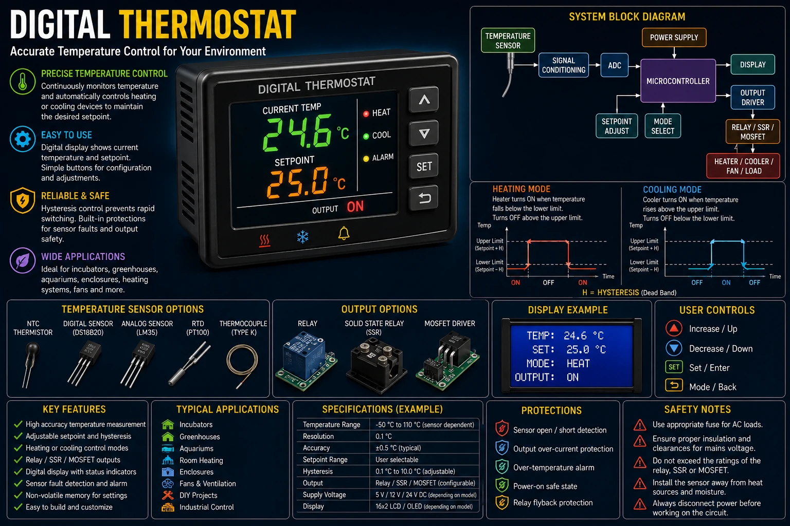
Project Overview
A thermostat continuously measures the temperature and compares it with a selected target temperature called the setpoint.
Temperature Sensor
        │
        ▼
Microcontroller
        │
        ├────► Digital Display
        │
        ├────► Setpoint Control
        │
        ▼
Control Logic
        │
        ▼
Relay / MOSFET / SSR
        │
        ▼
Heater or Fan
The controller switches the connected equipment on or off according to the measured temperature and the selected operating mode.
What Is a Thermostat?
A thermostat is a control system that maintains temperature within a desired range.
Instead of continuously measuring temperature without taking action, the thermostat uses the measurement to control another device.
For example, a heating thermostat can switch a heater on when the temperature falls below the setpoint and switch it off after the temperature rises sufficiently.
Temperature Sensor
The first stage of the thermostat is the temperature sensor.
Possible sensors include:
- NTC thermistors.
- Analog temperature sensors.
- Digital temperature sensors.
- RTDs.
- Thermocouples.
The choice depends on the required temperature range, accuracy, response time and circuit complexity.
Digital Temperature Sensors
A digital temperature sensor can provide a temperature reading directly to a microcontroller through a digital interface.
Temperature
     │
     ▼
Digital Sensor
     │
     ▼
Microcontroller
     │
     ▼
Control Algorithm
This can simplify the analog circuitry required by the thermostat.
NTC Thermistor
An NTC thermistor is a resistor whose resistance decreases as temperature increases.
It can be combined with another resistor to form a voltage divider.
VCC
 │
 R
 │
 ├────► ADC
 │
 NTC
 │
GND
The microcontroller can determine the temperature from the measured voltage and the thermistor characteristics.
Temperature Measurement
When using an analog sensor, the microcontroller's ADC converts the sensor voltage into a digital value.
Temperature
     │
     ▼
Sensor Voltage
     │
     ▼
ADC
     │
     ▼
Digital Value
     │
     ▼
Temperature Calculation
The software then converts the measured value into degrees Celsius or another desired temperature unit.
Setpoint
The setpoint is the desired temperature.
For example:
Setpoint = 25 °C
The controller compares the measured temperature with this value.
The setpoint can be adjusted using push buttons, a rotary encoder, potentiometer or another user interface.
Heating Control
In heating mode, the heater should normally turn on when the temperature falls below the control range.
Temperature falls
       │
       ▼
Below setpoint
       │
       ▼
Heater ON
       │
       ▼
Temperature rises
       │
       ▼
Upper limit reached
       │
       ▼
Heater OFF
Cooling Control
A thermostat can also control a cooling device such as a fan or compressor.
Temperature rises
       │
       ▼
Above setpoint
       │
       ▼
Cooling ON
       │
       ▼
Temperature falls
       │
       ▼
Lower limit reached
       │
       ▼
Cooling OFF
Hysteresis
Hysteresis prevents the output from rapidly switching on and off when the measured temperature is very close to the setpoint.
For example, a heating thermostat might use:
Setpoint = 25 °C
Hysteresis = 1 °C

Heater ON  below 24 °C
Heater OFF above 26 °C
The exact limits can be selected according to the application.
Why Hysteresis Is Important
Without hysteresis, a controller could behave like this:
25.00 °C → OFF
24.99 °C → ON
25.00 °C → OFF
24.99 °C → ON
25.00 °C → OFF
This rapid switching is undesirable for relays, heaters and other equipment.
Hysteresis creates a dead band in which the existing output state is maintained.
Relay Output
A relay can provide electrical isolation between the low-voltage controller and the controlled load.
Microcontroller
      │
      ▼
Transistor Driver
      │
      ▼
Relay Coil
      │
      ▼
Relay Contacts
      │
      ▼
Load
A transistor or MOSFET is normally used to drive the relay coil.
Relay Flyback Protection
A relay coil is inductive and can generate a high-voltage pulse when its current is switched off.
A flyback diode can be placed across a suitable DC relay coil to protect the switching transistor.
        Relay Coil
       ┌───────┐
VCC ────┤       ├────► Transistor
       └───────┘
          │ │
          └─┴─ Diode
The diode must be oriented so that it does not conduct during normal coil operation.
Solid-State Relay
A solid-state relay can be used instead of a mechanical relay.
Advantages can include:
- No mechanical contacts.
- Silent operation.
- Fast switching.
- Long operating life.
The SSR must be correctly rated for the load voltage, current and switching requirements.
MOSFET Output
For low-voltage DC loads, a MOSFET can often be used directly instead of a relay.
Microcontroller
      │
      ▼
Gate Driver
      │
      ▼
MOSFET
      │
      ▼
DC Heater / Fan


A logic-level MOSFET may be appropriate when it can be fully enhanced
by the available gate voltage.
Display
The display can show the current temperature and the selected setpoint.
┌──────────────────────┐ │ CURRENT 24.8 °C │ │ SETPOINT 25.0 °C │ │ MODE HEAT │ │ OUTPUT ON │ └──────────────────────┘
Additional information such as minimum temperature, maximum temperature or output status can also be displayed.
User Controls
Simple push buttons can provide temperature adjustment.
UP ▲ │ SETPOINT │ ▼ DOWN
A rotary encoder provides another convenient method of changing the setpoint.
Control Algorithm
A simple thermostat can use an on/off control algorithm.
Read Temperature │ ▼ Compare With Setpoint │ ├── Heating Mode │ └── Cooling Mode │ ▼ Apply Hysteresis │ ▼ Control Output
This approach is simple, reliable and suitable for many temperature control applications.
Heating Example
Suppose the thermostat is configured for:
Setpoint = 30 °C Hysteresis = 2 °C
The heater can be controlled as follows:
Temperature < 28 °C │ ▼ Heater ON Temperature > 32 °C │ ▼ Heater OFF
Between the two limits, the existing output state is maintained.
Cooling Example
For cooling:
Setpoint = 25 °C Hysteresis = 2 °C
The cooling output could operate as follows:
Temperature > 27 °C │ ▼ Cooling ON Temperature < 23 °C │ ▼ Cooling OFF
Temperature Calibration
The sensor should be compared against a known temperature reference if accurate measurements are required.
A simple calibration can establish an offset:
Corrected Temperature = Measured Temperature + Offset
More advanced calibration can use multiple points to compensate for sensor non-linearity.
Sampling Interval
The temperature does not normally change as quickly as an electrical signal.
Therefore the sensor does not necessarily need to be read thousands of times per second.
A practical thermostat can use a relatively slow measurement interval while still responding quickly enough for the thermal system.
Temperature Averaging
Temperature measurements can fluctuate because of electrical noise or sensor resolution.
A moving average can smooth the displayed value.
Average = (T1 + T2 + T3 + T4) / 4
The averaging period should not be so long that it causes an unwanted delay in the control response.
Minimum ON and OFF Times
Some loads should not be switched rapidly.
A thermostat can therefore impose minimum ON and OFF times.
This is particularly important for equipment such as refrigeration compressors, where rapid cycling can be undesirable.
Sensor Placement
Sensor placement has a major effect on thermostat performance.
- Keep the sensor away from the controller's own heat sources.
- Allow air or the monitored material to reach the sensor.
- Avoid direct heating from power components.
- Protect the sensor from moisture where necessary.
- Use suitable thermal coupling for the application.
Fan Control
The thermostat can control a cooling fan according to temperature.
For example:
Temperature > 35 °C │ ▼ Fan ON Temperature < 30 °C │ ▼ Fan OFF
The difference between the ON and OFF temperatures provides hysteresis.
Alarm Function
An additional alarm can warn the user when the temperature exceeds a critical limit.
Temperature │ ▼ Above Alarm Limit │ ├────► Buzzer │ └────► Display Warning
The alarm limit should be independent from the normal control setpoint when the application requires additional protection.
EEPROM Setpoint Storage
A microcontroller can store the selected setpoint in non-volatile memory.
The thermostat can therefore restore the previous setting after a power interruption.
Write frequency should be controlled so that the memory is not unnecessarily written every measurement cycle.
Power Supply
The controller requires a stable low-voltage power supply.
The supply should provide adequate regulation and filtering for the microcontroller, sensor and display.
If a relay or other load is switched, its electrical noise should be prevented from disturbing the controller supply.
Protection
The thermostat should include appropriate protection for both the electronics and the controlled load.
- Input fuse.
- Reverse-polarity protection where appropriate.
- Relay driver protection.
- Sensor fault detection.
- Over-temperature alarm.
- Output overload protection.
Sensor Failure Detection
A failed or disconnected sensor should not cause the controller to operate the heater indefinitely.
The software can detect readings outside the valid sensor range and enter a safe state.
Invalid Sensor Reading │ ▼ Disable Heater │ ▼ Display SENSOR ERROR
Fail-Safe Operation
The controlled output should default to a safe state when the microcontroller loses power or detects a serious fault.
For a heating system, this normally means preventing uncontrolled heating.
PCB Layout
Keep the sensor and analog measurement circuitry away from relay contacts and high-current switching paths.
- Use short sensor connections.
- Separate noisy power paths from sensor wiring.
- Provide suitable decoupling capacitors.
- Keep relay switching currents away from the sensor ground.
- Use adequate PCB spacing for the load voltage.
Testing the Thermostat
- Inspect the PCB.
- Verify the power supply.
- Check the temperature sensor.
- Verify the displayed temperature.
- Adjust the setpoint.
- Test heating mode.
- Test cooling mode if provided.
- Verify hysteresis.
- Test the output driver.
- Test sensor-failure detection.
- Test the alarm.
- Verify operation after a power interruption.
Troubleshooting
Temperature Reading Is Wrong
- Check the sensor wiring.
- Check the sensor type selected in software.
- Check calibration.
- Check the reference voltage.
- Check sensor placement.
Output Switches Rapidly
- Increase hysteresis.
- Check sensor noise.
- Add appropriate filtering.
- Check the control algorithm.
Heater Never Turns On
- Check the setpoint.
- Check the operating mode.
- Check the relay or MOSFET driver.
- Check the output protection.
- Check the temperature reading.
Heater Never Turns Off
- Check the temperature sensor.
- Check the control logic.
- Check the relay contacts.
- Check the MOSFET.
- Check the fail-safe logic.
Display Resets
- Check the power supply.
- Check relay switching noise.
- Add or improve decoupling.
- Check the controller ground.
- Check for excessive load current.
Common Mistakes
- Placing the temperature sensor near a heat-generating component.
- Using insufficient hysteresis.
- Ignoring sensor failure.
- Driving a relay directly from a microcontroller pin.
- Failing to provide relay-coil suppression.
- Ignoring load protection.
- Using inadequate PCB spacing for mains loads.
- Allowing uncontrolled heating after a controller failure.
Applications
- Room temperature control.
- Incubators.
- Equipment cooling.
- Enclosures.
- Greenhouses.
- Heating systems.
- Fan controllers.
- Laboratory equipment.
- Battery and electronics cooling.
- DIY automation systems.
Safety Notes
- Use only appropriately rated switching devices for the controlled load.
- Mains-voltage loads require suitable isolation and enclosure design.
- Use an appropriately rated fuse or circuit breaker.
- Maintain adequate creepage and clearance on the PCB.
- Never expose mains terminals to accidental contact.
- Do not rely on software alone for critical safety protection.
- Disconnect power before servicing the controlled circuit.
- Use suitable relay or solid-state switching components.
Skills Learned
- Temperature sensing.
- ADC measurement.
- Digital temperature processing.
- Thermostat control.
- Hysteresis.
- Relay control.
- MOSFET switching.
- Sensor calibration.
- Fault detection.
- Automatic temperature control.
Key Points
- A thermostat compares measured temperature with a desired setpoint.
- Hysteresis prevents rapid output switching.
- Temperature sensors can be analog or digital.
- Relays, MOSFETs or solid-state relays can control the load.
- Sensor placement strongly affects measurement accuracy.
- Sensor-failure detection is important for safe operation.
- Minimum ON and OFF times can protect certain loads.
- Temperature averaging can reduce measurement noise.
- The output should default to a safe state during serious faults.
- Mains-connected loads require proper electrical isolation and protection.