
Build a Digital Electronic Load
A digital electronic load is a programmable test instrument that draws a controlled amount of current from a power source. It can be used to test power supplies, batteries, chargers, DC converters and other power electronics. This project combines a power MOSFET, current sensing, control circuitry and digital measurement to create a useful laboratory test instrument.
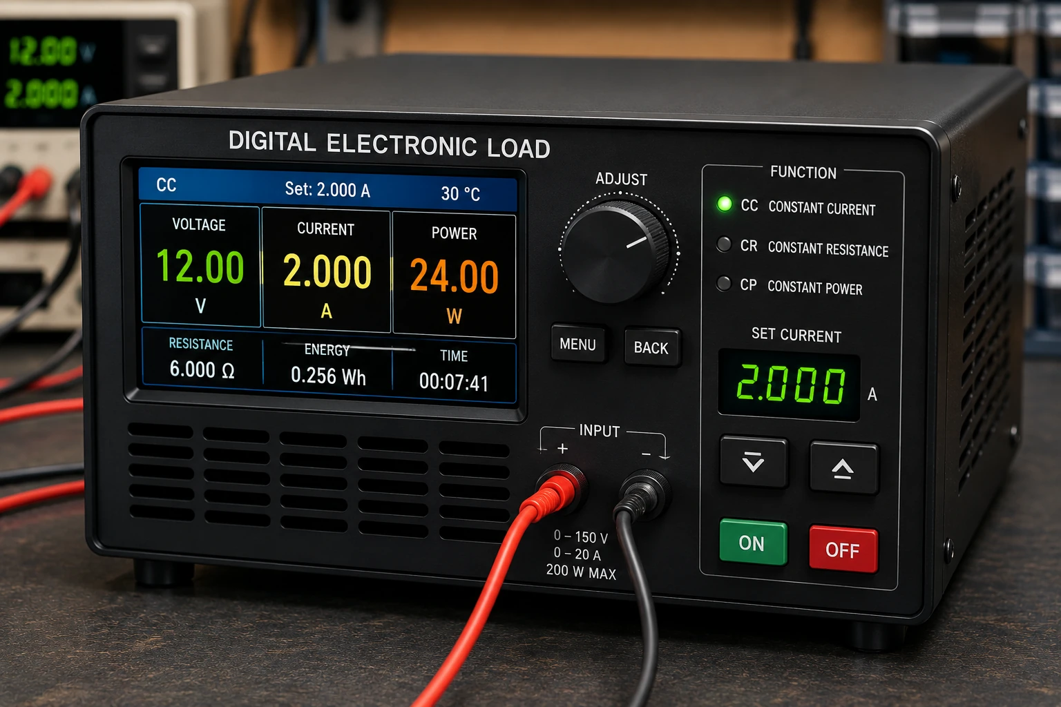
Project Overview
A conventional resistor can be used as a load, but its current changes when the supply voltage changes.
An electronic load solves this problem by actively controlling the current drawn from the source.
Power Supply
     │
     ▼
Electronic Load
     │
     ├── Current Measurement
     │
     ├── Voltage Measurement
     │
     └── Control Circuit
The load can maintain a selected current over a useful range of input voltages.
Why Use an Electronic Load?
Electronic loads are particularly useful when testing power supplies and batteries.
- Test maximum output current.
- Measure power-supply voltage regulation.
- Test battery capacity.
- Test USB power supplies.
- Test DC-DC converters.
- Measure charger performance.
- Perform controlled discharge tests.
Constant-Current Operation
The most common operating mode for a simple electronic load is constant current.
For example, if the load is set to 2 A, the control circuit attempts to maintain approximately 2 A even if the input voltage changes.
Set Current
    │
    ▼
Control Circuit
    │
    ▼
MOSFET
    │
    ▼
Load Current
    │
    ▼
Current Sensor
    │
    └──────────► Feedback
This feedback loop continuously compares the measured current with the desired current.
Basic Electronic Load
A simple constant-current electronic load can be constructed using a power MOSFET and an operational amplifier.
             + Supply
                 │
                 │
              DUT +
                 │
                 │
              MOSFET
                 │
                 ▼
            Current Sense
              Resistor
                 │
                 │
                GND

             ▲
             │
        Op-Amp Control
             ▲
             │
      Current Feedback
The MOSFET operates in its linear region and continuously adjusts its conduction to maintain the desired current.
MOSFET as the Load Element
The power MOSFET is the component that dissipates most of the power.
Unlike a MOSFET used only as an ON/OFF switch, the MOSFET in a linear electronic load may operate partially turned on.
The voltage across the MOSFET and the current flowing through it are both important.
Power = Voltage × Current

P = V × I
For example, if the MOSFET has 20 V across it while carrying 3 A:
P = 20 × 3
P = 60 W
That is a substantial amount of heat and requires appropriate thermal design.
Current-Sense Resistor
The control circuit needs a way to measure the load current.
A low-value precision resistor can be placed in series with the load.
Current
   │
   ▼
┌─────────┐
│  Sense  │
│ Resistor│
└─────────┘
   │
   ▼
Ground
The voltage across the resistor is proportional to the current.
V = I × R
For example, with a 0.1 Ω resistor and 2 A:
V = 2 × 0.1
V = 0.2 V
The control circuit can use this voltage as its feedback signal.
Sense Resistor Power
The current-sense resistor also dissipates power.
P = I²R
For a 0.1 Ω resistor carrying 2 A:
P = 2² × 0.1
P = 0.4 W
A resistor with an adequate power rating and suitable temperature coefficient should be used.
Op-Amp Control
An operational amplifier can compare the voltage across the sense resistor with a reference voltage.
Reference Voltage
       │
       ▼
    ┌──────┐
    │ Op   │────► MOSFET Gate
    │ Amp  │
    └──┬───┘
       ▲
       │
Sense Voltage
If the current is too low, the control circuit increases MOSFET conduction.
If the current becomes too high, it reduces MOSFET conduction.
This feedback mechanism keeps the current close to the selected value.
Setting the Current
If the control circuit regulates the sense voltage to a known reference value, the load current can be calculated from:
I = Vsense / Rsense
For example, with:
Vsense = 0.2 V
Rsense = 0.1 Ω
the current is:
I = 0.2 / 0.1
I = 2 A
Digital Current Control
A microcontroller can replace the manual current-setting potentiometer and provide digital control.
Buttons / Encoder
       │
       ▼
Microcontroller
       │
       ▼
DAC / PWM Filter
       │
       ▼
Op-Amp Control
       │
       ▼
MOSFET
This allows the user to select a precise current from a digital interface.
PWM Control
A microcontroller without a dedicated DAC can generate PWM and filter the signal to produce a control voltage.
PWM
 │
 ▼
RC Filter
 │
 ▼
DC Control Voltage
 │
 ▼
Current Regulator
The filtering must be sufficient to prevent excessive PWM ripple from appearing in the load current.
Voltage Measurement
A digital electronic load can also measure the voltage applied to its input.
A resistor divider can reduce the input voltage to a safe level for a microcontroller ADC.
Input Voltage
     │
     R1
     │
     ├────► ADC
     │
     R2
     │
    GND
The resistor values must be selected so that the ADC input remains within its permitted voltage range.
Power Measurement
Once voltage and current are measured, the controller can calculate power.
P = V × I
For example:
V = 12 V
I = 3 A

P = 12 × 3
P = 36 W
The display can show voltage, current and power simultaneously.
Energy Measurement
A digital electronic load can also calculate accumulated energy.
By measuring power over time, the controller can estimate the energy consumed during a test.
Energy = Power × Time
This is particularly useful when testing batteries and power banks.
Battery Capacity Testing
The electronic load can discharge a battery at a controlled current.
Battery │ ▼ Electronic Load │ ▼ Current Control │ ▼ Voltage MonitoringThe controller can stop the test when the battery reaches a defined cutoff voltage.
The measured discharge time and current can then be used to estimate capacity.
Capacity ≈ Current × TimeReal battery capacity depends on discharge conditions, temperature, battery chemistry and cutoff voltage.
Thermal Design
Heat is one of the most important design considerations in a linear electronic load.
The MOSFET may need to dissipate tens or even hundreds of watts depending on the design.
A substantial heatsink may therefore be required.
MOSFET │ ▼ Thermal Interface │ ▼ Heatsink │ ▼ Airflow ```Forced-air cooling can significantly increase the safe continuous power capability.
MOSFET Temperature
A temperature sensor can be attached to the heatsink.
The controller can reduce the load current or stop the test if the temperature becomes excessive.
Temperature Sensor │ ▼ Microcontroller │ ├──► Display Temperature │ └──► Reduce / Disable Load
Thermal protection is particularly important during unattended battery or power-supply testing.
Safe Operating Area
A power MOSFET cannot necessarily dissipate its maximum rated power at every combination of voltage and current.
The device's Safe Operating Area, or SOA, must be checked when using a MOSFET in linear operation.
This is especially important because many modern switching MOSFETs are optimized for switching rather than continuous linear operation.
The manufacturer's datasheet should be consulted when selecting the MOSFET.
Cooling Fan
A fan can be controlled automatically according to heatsink temperature.
Temperature │ ▼ Controller │ ▼ Fan Driver │ ▼ Cooling Fan
The fan can remain off at low temperatures and increase its speed when the load becomes hotter.
Display
A digital load can use an LCD, OLED or TFT display.
Useful information includes:
- Input voltage.
- Load current.
- Power.
- Temperature.
- Accumulated energy.
- Operating mode.
Constant-Resistance Mode
A more advanced electronic load can emulate a resistance.
The controller adjusts the current according to the measured voltage.
I = V / R
For example, if the programmed resistance is 10 Ω and the input voltage is 20 V:
I = 20 / 10 I = 2 A
The required current therefore changes as the input voltage changes.
Constant-Power Mode
An advanced load can also maintain approximately constant power.
P = V × I Therefore: I = P / V
If the programmed power is 40 W and the input voltage is 20 V:
I = 40 / 20 I = 2 A
If the voltage falls to 10 V, the controller would attempt to draw:
I = 40 / 10 I = 4 A
The current limit of the hardware must always take priority.
Over-Voltage Protection
The input voltage should be monitored continuously.
If the voltage exceeds the safe operating range, the load should disconnect or reduce its current.
Over-Current Protection
The hardware should also have a maximum current limit.
A software setting alone should not be relied upon as the only protection against excessive current.
The analog control circuit can provide an independent current limit.
Reverse Polarity Protection
If the electronic load is connected to a DC source, accidental reverse polarity can damage the circuit.
Depending on the design, protection can be implemented using:
- Series diode.
- MOSFET reverse-polarity protection.
- Fuse.
- Dedicated protection circuit.
Testing a Power Supply
The electronic load can be connected to the output of a DC power supply.
Increase the current gradually while monitoring voltage, current and temperature.
Power Supply │ ▼ Electronic Load │ ├── Voltage ├── Current ├── Power └── Temperature
This allows the regulation and thermal performance of the power supply to be evaluated.
Testing a DC-DC Converter
An electronic load is particularly useful for testing DC-DC converters.
The load can be increased gradually while measuring the converter's output voltage and current.
Efficiency can also be calculated if the input voltage and input current are measured.
Input Power = Vin × Iin Output Power = Vout × Iout Efficiency = Output Power / Input Power × 100%
Testing the Electronic Load
Start testing with a low-voltage source and a low current setting.
- Check the supply voltage.
- Verify the current-sense resistor.
- Check the MOSFET orientation.
- Set the current to a low value.
- Connect a suitable test source.
- Measure the actual current independently.
- Check the MOSFET temperature.
- Increase the load gradually.
Calibration
The voltage and current measurements should be calibrated against known reference instruments.
For current calibration, use a trusted multimeter or other appropriate current measurement method.
For voltage calibration, compare the displayed voltage with a known accurate meter.
Calibration constants can then be stored in the controller.
Troubleshooting
Current Is Too High
- Check the current-sense resistor.
- Check the feedback polarity.
- Check the reference voltage.
- Check the MOSFET control circuit.
- Verify the current calibration.
Current Is Unstable
- Check control-loop stability.
- Improve supply decoupling.
- Check the sense wiring.
- Reduce noise on the feedback signal.
- Review the compensation network.
MOSFET Gets Too Hot
- Reduce the load current.
- Reduce the voltage across the MOSFET.
- Improve heatsinking.
- Increase airflow.
- Check the MOSFET SOA.
Display Shows Incorrect Current
- Check the sense resistor value.
- Check the ADC reference.
- Check the current calibration.
- Check the sense amplifier.
Common Mistakes
- Using a MOSFET without checking its linear SOA.
- Using an undersized heatsink.
- Ignoring MOSFET temperature.
- Using an inaccurate current-sense resistor.
- Connecting excessive voltage to the input.
- Allowing the ADC input to exceed its permitted voltage.
- Relying entirely on software protection.
- Testing high power without adequate cooling.
Safety Notes
- Start testing at low voltage and low current.
- Never exceed the voltage and current ratings of the load.
- Use an adequately rated heatsink.
- Provide forced cooling when required.
- Never touch an energized high-power circuit.
- Large capacitors can remain charged after power is removed.
- Use suitable fuses and current limiting.
- Do not connect a load directly to mains voltage.
- When testing mains-powered supplies, use appropriate isolation and safety equipment.
Skills Learned
- Constant-current regulation.
- Power MOSFET control.
- Current sensing.
- Operational amplifier feedback.
- ADC voltage measurement.
- Digital instrumentation.
- Power dissipation calculations.
- Heatsink design.
- Battery testing.
- Power-supply testing.
Key Points
- An electronic load actively controls the current drawn from a power source.
- A MOSFET is commonly used as the controllable load element.
- The current-sense resistor provides feedback to the control circuit.
- Power dissipation is calculated from voltage multiplied by current.
- Linear MOSFET operation requires careful SOA checking.
- Thermal management is critical at high power.
- A microcontroller can provide digital control and measurement.
- Voltage, current, power and temperature can be displayed together.
- Advanced loads can support constant-current, constant-resistance and constant-power modes.
- Independent hardware protection should complement software protection.