
Build a 300 W Flyback SMPS
A flyback converter is a versatile switch-mode power supply topology that stores energy in a magnetic component while the switching device is conducting and transfers that stored energy to the output when the switch turns off. This project explores a high-power 300 W flyback architecture using a PWM controller, power MOSFET, flyback transformer, secondary rectifier, output filter and feedback circuit.
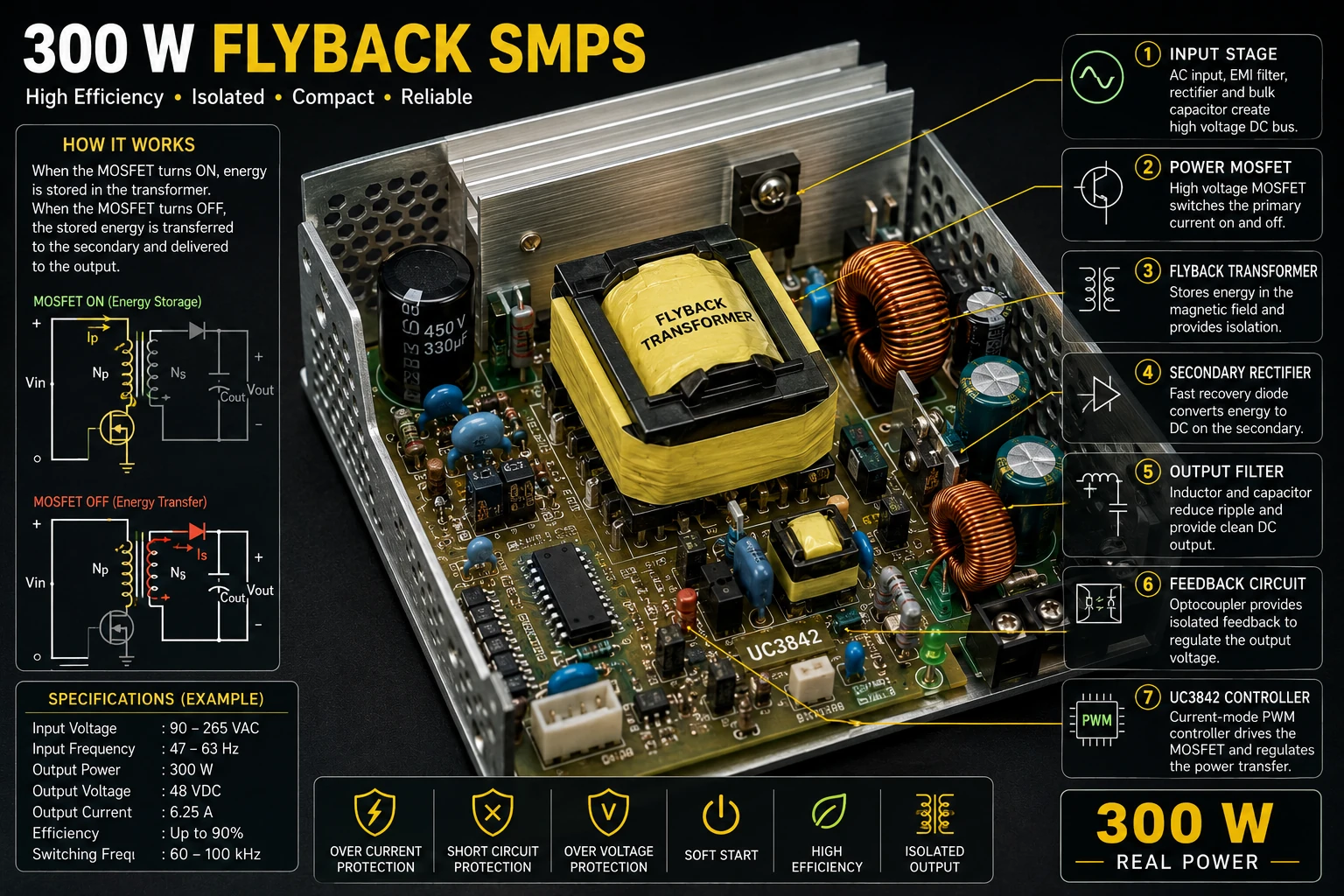
Project Overview
A flyback converter differs from many other isolated converter topologies because energy is stored in the magnetic field of the transformer during one part of the switching cycle and delivered to the secondary during another part of the cycle.
DC Input │ ▼ Flyback Transformer │ ▼ Switching MOSFET │ ▼ PWM Controller │ ▼ FeedbackThe controller continuously adjusts the switching operation to regulate the output voltage.
How a Flyback Converter Works
During the MOSFET ON period, current flows through the primary winding and energy is stored in the transformer's magnetic field.
MOSFET ON Input │ ▼ Primary Winding │ ▼ MOSFET │ GND Energy is stored in the magnetic field.
When the MOSFET turns OFF, the magnetic field collapses and the transformer polarity changes. Energy is then transferred to the secondary side.
MOSFET OFF Transformer │ ▼ Secondary Rectifier │ ▼ Output Capacitor │ ▼ Load
Basic Flyback Architecture
AC Mains │ ▼ EMI Filter │ ▼ Bridge Rectifier │ ▼ Bulk Capacitor │ ▼ DC Bus │ ▼ Primary Winding │ ▼ MOSFET │ ▼ Current Sense │ ▼ Ground Secondary │ ▼ Fast Rectifier │ ▼ Output Filter │ ▼ DC Output
An isolated feedback circuit transfers output-voltage information back to the primary controller.
UC3842 Controller
The UC3842 is a current-mode PWM controller commonly used in switch-mode power supplies.
It provides functions required to control the switching transistor, including oscillator timing, current sensing and PWM control.
Timing Network │ ▼ UC3842 │ ▼ Gate Drive │ ▼ Power MOSFET ```The controller can respond rapidly to changes in primary current and provide cycle-by-cycle current limiting.
Power MOSFET
The MOSFET is the primary switching device.
It repeatedly switches the primary current on and off at the operating frequency.
The MOSFET must be selected according to:
- Maximum drain-source voltage.
- Peak drain current.
- Conduction loss.
- Switching loss.
- Safe Operating Area.
- Thermal requirements.
For an offline converter, the voltage stress can be substantially higher than the rectified mains voltage because of transformer leakage inductance and reflected secondary voltage.
Primary Current Sensing
The UC3842 uses a current-sense signal to monitor the primary switching current.
Primary Current │ ▼ Sense Resistor │ ▼ Current Sense Input │ ▼ UC3842 ```The current-sense resistor converts the switching current into a voltage.
Vsense = Iprimary × RsenseWhen the current reaches the programmed limit, the controller reduces or terminates the switching pulse.
Flyback Transformer
The flyback transformer is actually a coupled energy-storage inductor. Its magnetic design is therefore different from that of a conventional 50 Hz transformer.
The core must store the required energy without excessive saturation.
Important design parameters include:
- Core material.
- Effective core area.
- Air gap.
- Primary inductance.
- Primary turns.
- Secondary turns.
- Maximum flux density.
- Switching frequency.
- Maximum primary current.
The Air Gap
A deliberate air gap is normally introduced into a flyback magnetic core.
The gap allows the magnetic component to store substantial energy without reaching saturation too quickly.
The required gap depends on the core, inductance, peak current and operating conditions.
The magnetic design should be calculated from the core manufacturer's data rather than estimated from physical dimensions alone.
Stored Energy
The energy stored in the primary inductance is approximately:
E = ½ × L × I²
where:
- E is stored energy.
- L is primary inductance.
- I is peak primary current.
At high power, even a relatively small amount of energy per switching cycle becomes significant because the converter operates thousands of cycles per second.
Switching Frequency
The switching frequency determines how often energy is transferred from the primary to the secondary.
Higher frequency can reduce magnetic-component size but generally increases switching losses and electromagnetic interference.
The practical operating frequency must therefore be selected as a trade-off between magnetic size, efficiency, switching loss and EMI.
Duty Cycle
The duty cycle determines how long the MOSFET remains conducting during each switching cycle.
Period ┌──────────────────────────────┐ │██████████ │ │ ON │ OFF │ └──────────────────────────────┘ Duty Cycle
The actual duty-cycle relationship depends on the flyback topology, input voltage, reflected output voltage and operating mode.
Primary Voltage Stress
When the MOSFET switches off, the drain voltage can rise rapidly.
The drain voltage is influenced by the input voltage, reflected secondary voltage and leakage-inductance spike.
Drain Voltage /\ Leakage Spike / \ ──────/ \────────────── │ │ Reflected Voltage │ ──────┴──────────────────── Time ```The MOSFET must therefore have sufficient voltage margin.
RCD Snubber
An RCD snubber can be used to absorb energy associated with leakage inductance and limit the MOSFET drain-voltage spike.
Drain │ ├──── R ──── C │ │ └──── D ──────┘ ```The component values should be selected from measured switching waveforms and the actual transformer characteristics.
Secondary Rectifier
When the MOSFET turns off, energy is transferred to the secondary winding.
A suitable fast rectifier converts this energy into a unidirectional current.
Transformer Secondary │ ▼ Fast Diode │ ▼ Output Capacitor │ ▼ Load
The diode must withstand the required reverse voltage and forward current while keeping losses within acceptable limits.
Output Filter
The secondary rectifier produces pulsed current.
An output capacitor and, where appropriate, an inductor reduce ripple and provide a stable DC output.
Rectifier │ ▼ Inductor │ ├──── Capacitor ─── GND │ ▼ Output
Feedback Regulation
The output voltage must be monitored so that the controller can adjust the amount of energy transferred during each switching cycle.
An optocoupler can provide isolated feedback between the secondary and primary sides.
Output │ ▼ Voltage Reference │ ▼ Error Amplifier │ ▼ Optocoupler │ ▼ UC3842 │ ▼ MOSFET ```If the output voltage rises above its target, the feedback system reduces the energy transferred to the output.
Current-Mode Control
The UC3842 uses current-mode control.
Each switching cycle can be terminated when the sensed primary current reaches the control threshold.
This provides fast response to load changes and also assists with primary current limiting.
Startup Supply
The controller requires a suitable startup supply before it can begin switching.
After startup, an auxiliary winding can provide operating power to the controller.
High-Voltage DC │ ▼ Startup Resistor │ ▼ UC3842 VCC │ ▼ Switching Starts │ ▼ Auxiliary Winding │ └────► Controller Supply
The startup resistor must be appropriately rated for the voltage and power involved.
Auxiliary Winding
A winding on the flyback transformer can provide isolated low-voltage power for the controller and other primary-side circuitry.
This allows the high-value startup supply to be used mainly during the initial startup phase.
Soft Start
The converter should establish operation in a controlled manner rather than immediately demanding maximum energy transfer.
A suitable startup strategy reduces stress on the switching transistor, transformer and output components.
Over-Current Protection
Over-current protection is particularly important in a flyback converter because excessive primary current can rapidly saturate the magnetic core and damage the MOSFET.
The current-sense circuit should therefore be designed with an appropriate maximum current limit.
Short-Circuit Protection
A short circuit on the output can cause the converter to repeatedly reach its primary current limit.
A practical design should enter a controlled protection state rather than operating continuously at the current limit.
Depending on the controller and design, this may involve shutdown, hiccup operation or another current-limiting strategy.
Over-Voltage Protection
An abnormal feedback condition could cause the converter to produce an excessive output voltage.
Additional over-voltage protection can provide another layer of safety for the connected equipment.
Thermal Management
At 300 W, power losses can become significant.
Heat may be generated by:
- Primary MOSFET.
- Secondary rectifier.
- Transformer windings.
- Transformer core.
- Sense resistor.
- Snubber components.
- Output inductor.
The enclosure and cooling system must be designed around the measured losses and operating temperature.
Efficiency
If the converter delivers 300 W at 90% efficiency:
Input Power = 300 / 0.90 Input Power ≈ 333 W
Approximately 33 W is then dissipated as heat.
Higher efficiency reduces the thermal load and improves overall system performance.
PCB Layout
Flyback converters contain high-current and high-voltage switching loops.
PCB layout therefore has a major effect on efficiency, voltage spikes, EMI and reliability.
- Keep the primary switching loop compact.
- Keep gate-drive connections short.
- Keep the current-sense path clean.
- Separate feedback circuitry from noisy switching nodes.
- Provide adequate creepage and clearance.
- Use appropriate copper widths.
- Keep high-voltage and low-voltage areas clearly separated.
EMI
Rapid switching edges can generate both conducted and radiated electromagnetic interference.
EMI can be reduced through appropriate filtering, layout, shielding and controlled switching transitions.
The final design should be evaluated under real operating conditions.
Testing the Flyback Converter
A high-power flyback converter should be brought up gradually.
- Inspect all components and solder joints.
- Verify transformer winding connections.
- Verify MOSFET orientation.
- Verify current-sense wiring.
- Check the UC3842 supply.
- Check the oscillator frequency.
- Verify the gate-drive waveform.
- Test the primary switching stage carefully.
- Check drain-voltage spikes.
- Apply a low output load initially.
- Increase the load gradually.
- Monitor temperature and waveforms.
Oscilloscope Measurements
Important waveforms include:
- UC3842 gate-drive output.
- MOSFET drain voltage.
- Primary current-sense waveform.
- Transformer auxiliary winding.
- Secondary rectifier waveform.
- Output ripple.
Measurements on an offline mains-powered converter require properly rated probes and suitable isolation procedures.
Troubleshooting
No Switching
- Check UC3842 VCC.
- Check startup resistor.
- Check timing components.
- Check controller wiring.
- Check current-sense input.
- Check for an active protection condition.
MOSFET Fails Immediately
- Check drain-voltage spikes.
- Check transformer polarity.
- Check primary inductance.
- Check current limit.
- Check snubber components.
- Check PCB layout.
Output Voltage Too High
- Check the feedback divider.
- Check the voltage reference.
- Check the optocoupler.
- Check feedback polarity.
- Check the controller feedback pin.
Transformer Overheats
- Check core selection.
- Check air gap.
- Check primary inductance.
- Check peak current.
- Check switching frequency.
- Check winding losses.
Output Ripple Is Excessive
- Check secondary rectifier.
- Check output capacitor.
- Check output inductor.
- Check switching frequency.
- Check PCB layout.
Common Design Mistakes
- Using an unsuitable flyback core.
- Insufficient air gap.
- Allowing the core to saturate.
- Ignoring leakage-inductance spikes.
- Using an undersized MOSFET.
- Ignoring secondary diode losses.
- Poor current-sense layout.
- Insufficient creepage and clearance.
- Testing immediately at full power.
- Failing to provide short-circuit protection.
Safety Notes
- This project can involve lethal mains voltage.
- The primary DC bus can remain charged after the supply is disconnected.
- Use appropriate fuses and protective enclosures.
- Maintain adequate creepage and clearance.
- Keep the primary and secondary circuits properly isolated.
- Use appropriately rated oscilloscope probes.
- Never touch an energized primary circuit.
- Discharge high-voltage capacitors safely before servicing.
- Use components with appropriate voltage, current and insulation ratings.
Skills Learned
- Flyback converter operation.
- UC3842 PWM control.
- Current-mode control.
- High-frequency magnetics.
- Power MOSFET switching.
- Transformer energy storage.
- Feedback regulation.
- Snubber design.
- SMPS protection.
- High-frequency PCB layout.
Key Points
- A flyback converter stores energy in its magnetic component during the switching cycle.
- The stored energy is transferred to the secondary when the MOSFET turns off.
- The UC3842 provides current-mode PWM control.
- The flyback transformer requires careful magnetic design and an appropriate air gap.
- Primary current sensing provides important control and protection.
- Leakage inductance can produce dangerous switching spikes.
- Snubbers or clamps may be required to protect the MOSFET.
- Feedback maintains the desired output voltage.
- Thermal management becomes important at several hundred watts.
- Offline flyback converters require careful high-voltage safety design.