
Build an FM Stereo Radio Receiver
An FM radio receiver captures frequency-modulated radio signals and converts them into an audible audio signal. This project introduces the main stages of an FM receiver, including the antenna, RF tuning, frequency conversion, FM demodulation, stereo decoding and audio amplification.
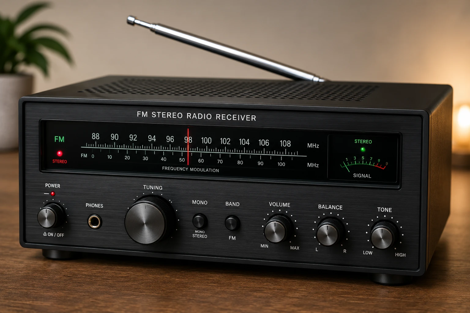
Project Overview
FM broadcasting is one of the most common methods used to transmit high-quality analog audio over radio.
Unlike AM broadcasting, where the carrier amplitude changes with the audio signal, FM changes the frequency of the carrier.
An FM receiver performs the reverse operation: it selects the desired radio station, extracts the frequency variations and converts them back into an audio signal.
FM Antenna
    │
    ▼
RF Tuner
    │
    ▼
Mixer / IF
    │
    ▼
FM Demodulator
    │
    ▼
Stereo Decoder
    │
    ▼
Audio Amplifier
    │
    ▼
Loudspeaker
How FM Works
In frequency modulation, the instantaneous frequency of a radio carrier changes according to the audio signal.
The amplitude of the carrier remains approximately constant while its frequency moves above and below the center frequency.
Audio Signal

       /\        /\
      /  \      /  \
_____/    \____/    \____


FM Carrier

))))))))  )))))  )))))))))
 ))))))))))  ))))))  )))))
))))  ))))))))))  )))))))))
A receiver measures these frequency variations and reconstructs the original audio waveform.
FM Broadcast Band
The exact FM broadcast frequency range depends on the country and broadcasting regulations.
A receiver must therefore be designed or configured for the frequency band used by local broadcasters.
The tuning section determines which station is selected from the available RF signals.
Main Receiver Stages
- Antenna
- RF input and filtering
- Tuning circuit
- Local oscillator
- Mixer
- Intermediate-frequency amplifier
- FM detector
- Stereo decoder
- Audio preamplifier
- Audio power amplifier
Not every practical receiver exposes all of these stages as separate circuits. Modern receiver ICs can integrate several stages into one device.
Antenna
The antenna captures electromagnetic energy from nearby FM broadcast stations.
For VHF FM reception, antenna dimensions and placement can have a significant effect on reception quality.
A simple wire antenna can be sufficient for strong local stations.
For weak signals, a properly positioned external antenna can provide substantially better reception.
RF Tuning
The antenna receives many radio signals simultaneously.
The tuning section selects the desired frequency while rejecting unwanted signals.
Antenna
   │
   ▼
RF Filter
   │
   ▼
Tuned Circuit
   │
   ▼
Selected Station
Older receivers often used variable capacitors for tuning. Modern receivers commonly use electronic tuning.
Superheterodyne Receiver
A traditional high-performance FM receiver commonly uses the superheterodyne principle.
The incoming station is mixed with a locally generated oscillator signal.
RF Signal ─────┐
              │
              ▼
           Mixer ─────► IF Signal
              ▲
              │
       Local Oscillator
The mixer produces several frequency components. The receiver selects the desired intermediate-frequency component for further processing.
Intermediate Frequency
Using a fixed intermediate frequency allows the receiver's filtering and amplification stages to be optimized for one frequency.
This makes it easier to achieve good selectivity and sensitivity over the entire tuning range.
A commonly encountered FM IF frequency is 10.7 MHz, although the actual architecture depends on the receiver design.
FM Demodulation
The FM detector converts changes in frequency into a corresponding audio-frequency voltage.
Several detector architectures have been used in FM receivers, including:
- Discriminator circuits.
- Ratio detectors.
- Quadrature detectors.
- PLL-based detectors.
- Integrated FM detector circuits.
Stereo FM
Stereo FM broadcasting allows two audio channels to be transmitted: left and right.
The broadcast signal contains a composite multiplex signal from which the two audio channels can be recovered.
FM Signal
    │
    ▼
FM Demodulator
    │
    ▼
Stereo Multiplex Signal
    │
    ▼
Stereo Decoder
    ├────────► Left
    │
    └────────► Right
Stereo Decoder
The stereo decoder separates the multiplexed broadcast information into left and right audio channels.
A stereo decoder may also provide a stereo indicator output that can be used to illuminate an LED when a valid stereo signal is detected.
Mono and Stereo Reception
A good receiver should continue producing useful audio when the received signal is too weak for reliable stereo decoding.
Switching to mono can reduce noise and improve listening quality in areas with weak reception.
Tuning
The receiver must be able to select different stations across its operating band.
Traditional receivers used mechanical tuning capacitors.
Modern designs may use:
- Varactor diodes.
- PLL frequency synthesis.
- Digital frequency control.
- Microcontroller-controlled tuning.
PLL Tuning
A phase-locked loop can generate a precisely controlled local oscillator frequency.
Reference
   │
   ▼
PLL ─────► Local Oscillator
   ▲
   │
Frequency Divider
The tuning frequency can be changed electronically, making PLL tuning particularly useful in digital FM receivers.
Audio Output
After demodulation and stereo decoding, the signal is still a relatively low-power audio signal.
An audio amplifier is therefore required to drive a loudspeaker.
Left ─────► Audio Amplifier ─────► Left Speaker

Right ────► Audio Amplifier ─────► Right Speaker
The amplifier can be a small integrated audio amplifier for a compact radio or a larger amplifier for a more powerful system.
Power Supply
The receiver requires a clean and stable power supply.
Noise from the power supply can enter sensitive RF and audio circuits.
- Use suitable supply filtering.
- Place bypass capacitors close to IC supply pins.
- Keep noisy digital circuits away from sensitive RF stages.
- Use a stable regulator where required.
RF Layout
FM receivers operate at relatively high frequencies, so PCB layout is important.
- Keep RF traces short.
- Avoid unnecessary long connections.
- Use appropriate grounding techniques.
- Keep the oscillator away from sensitive input circuits.
- Follow the component placement recommendations of the receiver IC.
A circuit that works well on a breadboard at low frequencies may not perform well when RF layout becomes important.
Using an FM Receiver IC
For a practical project, using a dedicated FM receiver IC is often much simpler than building every RF stage from individual transistors.
An integrated receiver may contain several functions such as:
- RF amplifier.
- Mixer.
- Local oscillator.
- IF amplifier.
- FM detector.
- Stereo decoder.
This makes integrated FM receiver circuits particularly suitable for compact DIY radio projects.
Testing the Receiver
Connect the antenna and power the receiver from a suitable supply.
Tune slowly across the FM broadcast band and listen for stations.
Strong stations should normally produce cleaner and louder audio than weak stations.
If a stereo indicator is provided, verify that it activates when a sufficiently strong stereo signal is received.
Troubleshooting
No Stations Received
- Check the antenna connection.
- Check the supply voltage.
- Check the tuning circuit.
- Check the receiver IC connections.
- Move the antenna to a better location.
Weak Reception
- Improve antenna placement.
- Use a suitable external antenna.
- Check RF grounding.
- Check the RF input components.
- Move the receiver away from electrical interference.
Heavy Noise
- Check the power supply filtering.
- Check antenna connections.
- Try mono reception.
- Move the antenna.
- Check for interference from nearby electronics.
No Stereo
- Check signal strength.
- Check the stereo decoder.
- Check the pilot signal path.
- Check the stereo indicator circuit.
- Verify the receiver configuration.
Common Applications
- DIY FM radios.
- Portable radios.
- Home audio systems.
- Car audio systems.
- Radio tuners.
- Audio receivers.
- Educational RF projects.
Safety Notes
- Use a suitable low-voltage DC supply for the receiver.
- Do not connect the antenna or circuit directly to mains voltage.
- Use suitable insulation when connecting external antennas.
- Follow local regulations for external antennas and RF equipment.
- Do not transmit RF signals unless the equipment and frequency are legally permitted.
Skills Learned
- FM modulation.
- Radio-frequency reception.
- RF filtering.
- Superheterodyne receivers.
- FM demodulation.
- Stereo decoding.
- Electronic tuning.
- RF PCB layout.
- Audio signal processing.
- Radio troubleshooting.
Key Points
- FM encodes audio information by varying carrier frequency.
- The antenna receives many signals simultaneously.
- The tuning system selects the desired station.
- A superheterodyne receiver can convert the selected signal to an intermediate frequency.
- The FM detector recovers the audio information.
- A stereo decoder separates the left and right channels.
- A clean power supply is important for sensitive RF circuits.
- Good PCB layout is especially important at radio frequencies.
- A dedicated FM receiver IC can simplify the design considerably.