
Build a Home Automation Hub
A home automation hub provides a central controller for sensors, switches, lights, fans and other connected devices. This project combines a microcontroller, wireless communication, sensor inputs and relay or solid-state outputs to create a flexible home automation platform.
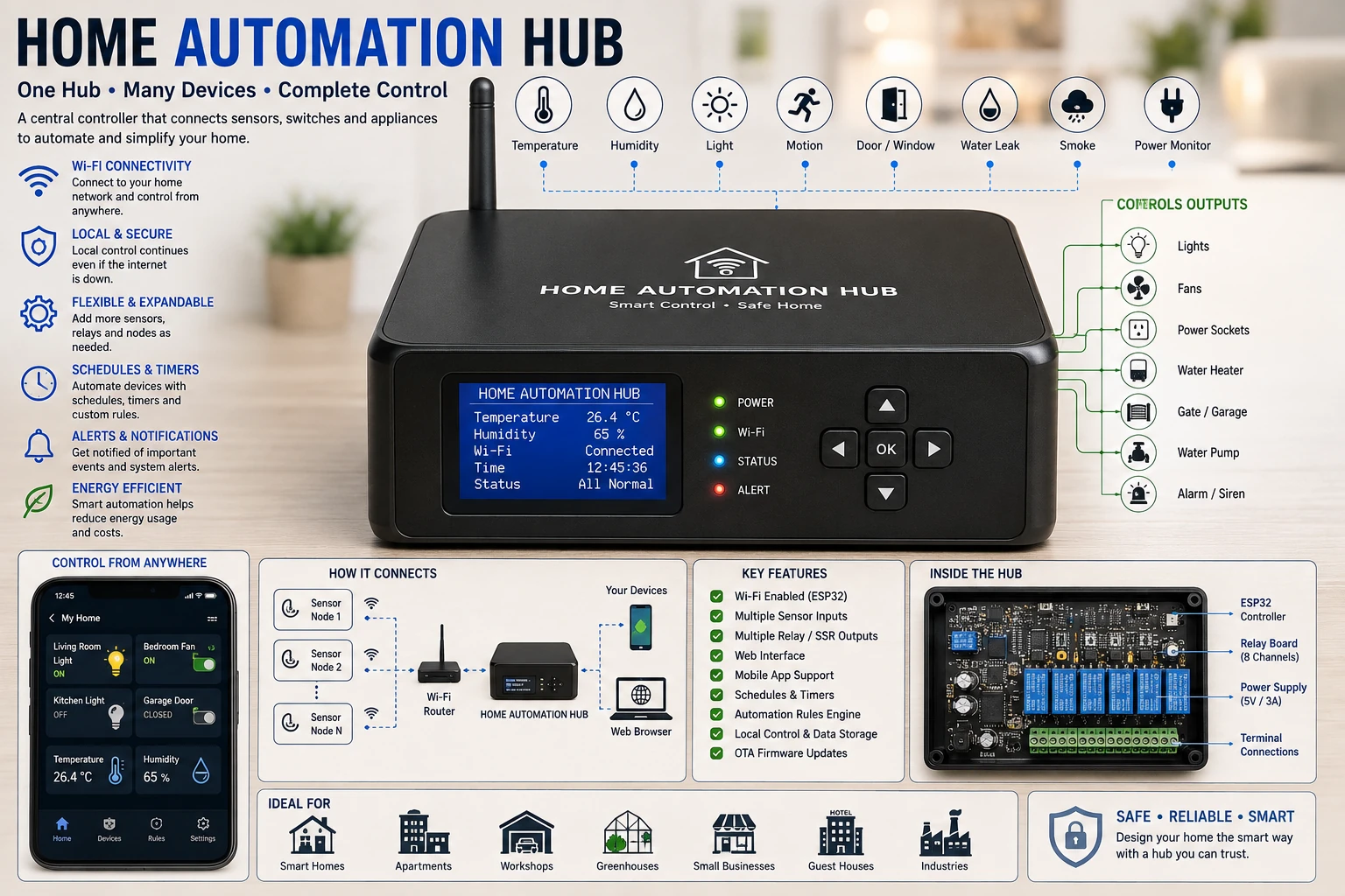
Project Overview
Instead of controlling each device independently, a central hub can collect information from sensors and coordinate multiple outputs.
             ┌── Temperature Sensor
             │
             ├── Motion Sensor
             │
             ├── Light Sensor
             │
             ├── Door Sensor
             │
             ▼
       Home Automation Hub
             │
       ┌─────┼─────┐
       ▼     ▼     ▼
    Lights  Fan   Relay
             │
             ▼
          Appliances
The hub can also provide a user interface through a display, physical buttons, local web page or wireless application.
Central Controller
An ESP32 or another suitable microcontroller can serve as the central controller.
The controller can manage:
- Sensor inputs.
- Relay outputs.
- Wireless communication.
- Timers.
- Automation rules.
- User commands.
- Device status.
Sensors
Sensors provide the information needed for automatic decisions.
Possible sensors include:
- Temperature sensors.
- Humidity sensors.
- Light sensors.
- Motion sensors.
- Door and window sensors.
- Air-quality sensors.
- Water-leak sensors.
- Smoke or environmental sensors.
Motion Detection
A PIR motion sensor can detect movement in a room.
PIR Sensor
    │
    ▼
Microcontroller
    │
    ▼
Automation Rule
    │
    ▼
Light ON
For example, a hallway light can be activated when motion is detected during a selected period.
Light Sensor
A light sensor can determine whether an environment is bright or dark.
Light Level
    │
    ▼
Sensor
    │
    ▼
Controller
    │
    ▼
Decision
    │
    ▼
Light Control
This allows lighting to be controlled according to actual ambient conditions.
Temperature Monitoring
A temperature sensor can be used to control fans, heaters or air circulation.
Temperature
     │
     ▼
Sensor
     │
     ▼
Automation Hub
     │
     ▼
Fan / Heater
The temperature control can use configurable thresholds and hysteresis.
Relay Outputs
Relay outputs allow the low-voltage controller to operate electrical loads.
ESP32
 │
 ▼
Driver
 │
 ▼
Relay
 │
 ▼
Electrical Load
The relay must be appropriately rated for the voltage, current and type of load being controlled.
Solid-State Outputs
Solid-state switching devices can be used where appropriate.
For low-voltage DC loads, a MOSFET can provide efficient electronic switching.
For other loads, a suitably rated solid-state relay may be used.
Wireless Communication
An ESP32-based hub can communicate with other devices through Wi-Fi.
Sensor Node
     │
     │ Wi-Fi
     ▼
Automation Hub
     │
     │ Wi-Fi
     ▼
Phone / Computer
The wireless architecture can be expanded with multiple sensor nodes depending on the requirements of the installation.
Local Web Interface
The hub can provide a local web interface for controlling connected devices.
┌────────────────────────────┐
│      HOME CONTROL          │
├────────────────────────────┤
│ Living Room   LIGHT   ON   │
│ Bedroom       LIGHT   OFF  │
│ Workshop      FAN     ON   │
│ Garage        RELAY   OFF  │
├────────────────────────────┤
│ Temperature       26.4 °C  │
│ Humidity             68 %  │
└────────────────────────────┘
A local interface avoids requiring a separate cloud service for basic control within the home network.
Manual Control
Physical buttons can be added to provide local control even when the network is unavailable.
Button
  │
  ▼
Microcontroller
  │
  ▼
Output
  │
  ▼
Relay / MOSFET
Manual controls are particularly useful for lights and frequently used appliances.
Automation Rules
The hub becomes useful when sensor information can trigger automatic actions.
IF Motion Detected
AND Time = Night

        THEN

Turn Hall Light ON
Rules can combine several conditions.
IF
Temperature > 30 °C
AND
Fan = Available

THEN
Fan ON
Timers
Devices can be controlled using timers.
Relay ON
   │
   ▼
Start Timer
   │
   ▼
Timer Expires
   │
   ▼
Relay OFF
This is useful for lights, fans and other devices that should operate for a limited period.
Schedules
A hub can automatically operate devices according to a schedule.
07:00
 │
 ├──► Kitchen Light ON
 │
18:00
 │
 ├──► Outdoor Light ON
 │
23:00
 │
 └──► Outdoor Light OFF
Schedules can be stored locally by the controller.
Scenes
Several devices can be controlled together as a scene.
For example, a "Night" scene could:
- Turn off selected lights.
- Turn on security lighting.
- Reduce fan speed.
- Enable selected sensors.
A scene simplifies control of multiple devices with a single command.
Device Status
The hub should maintain the current state of each connected output.
Living Room Light   ON
Bedroom Light       OFF
Workshop Fan        ON
Garage Relay        OFF
Displaying the actual state helps the user understand what the automation system is doing.
Temperature-Based Automation
A temperature sensor can automatically control a fan.
Temperature < 28 °C
        │
        ▼
     Fan OFF

Temperature > 30 °C
        │
        ▼
     Fan ON
The difference between the ON and OFF thresholds provides hysteresis.
Presence-Based Lighting
Motion detection can be combined with ambient light measurement.
Motion?
  │
  ├── NO ──► Nothing
  │
 YES
  │
  ▼
Is Room Dark?
  │
  ├── NO ──► Nothing
  │
 YES
  │
  ▼
Light ON
This avoids switching lights on unnecessarily when sufficient daylight is already available.
Door and Window Monitoring
Magnetic reed switches can detect whether a door or window is open.
Door
 │
 ▼
Magnetic Sensor
 │
 ▼
Controller
 │
 ├──► Display Status
 │
 └──► Alarm / Notification
Multiple sensors can be connected to a central hub.
Water-Leak Detection
A water sensor can detect the presence of unwanted water in areas such as utility rooms.
Leak Sensor
     │
     ▼
Automation Hub
     │
     ├──► Alarm
     │
     └──► Shutoff Control
The sensor should be positioned where a leak is likely to be detected early.
Alarm System
The hub can activate a buzzer or other indicator when a configured condition occurs.
Examples include:
- Water detected.
- Unexpected door opening.
- High temperature.
- Sensor failure.
- Abnormal operating condition.
Notification
A connected hub can send status information to another device through the network.
Possible notification methods depend on the communication system implemented by the project.
Sensitive automation functions should not be exposed to an unsecured public network.
Cloud Versus Local Control
A home automation system can be designed around local control, cloud services or a combination of both.
Local control offers an important advantage: basic automation can continue operating even if the Internet connection is unavailable.
Sensors
   │
   ▼
Local Hub
   │
   ├──► Local Automation
   │
   └──► Internet
            │
            ▼
       Remote Services
Internet Failure
The automation hub should preferably continue performing essential local rules when the Internet connection is unavailable.
For example, a local temperature-control rule should not necessarily stop working just because cloud communication is interrupted.
Wi-Fi Reconnection
Wireless connections can occasionally be interrupted.
Connected
   │
   ▼
Connection Lost
   │
   ▼
Reconnect
   │
   ▼
Connected Again
The firmware should handle reconnection without unnecessarily losing important automation states.
Power Failure
The hub should define what happens when power is restored.
Some outputs may need to remain OFF until the controller has completed startup and verified its operating conditions.
Critical loads should have hardware protection independent of the automation software.
Non-Volatile Settings
Automation settings can be stored in non-volatile memory.
Possible stored parameters include:
- Temperature thresholds.
- Timer durations.
- Device names.
- Schedules.
- Operating modes.
- Calibration values.
Write operations should be managed carefully to avoid unnecessary memory wear.
Clock and Timekeeping
Scheduled automation requires an accurate time source.
The hub can use a real-time clock or obtain time from a suitable network time source.
The system should also account for time being unavailable during startup or network failure.
Multiple Automation Nodes
Larger installations can use several sensor nodes communicating with a central hub.
Sensor Node 1 ──┐
Sensor Node 2 ──┤
Sensor Node 3 ──┼──► Central Hub
Sensor Node 4 ──┤
Sensor Node 5 ──┘
                       │
                       ▼
                 Automation Rules
                       │
                 ┌─────┼─────┐
                 ▼     ▼     ▼
               Light  Fan   Relay
This approach allows sensors to be located close to the areas they monitor.
Communication Protocol
The nodes and hub require a defined communication method.
Depending on the architecture, this can include simple HTTP requests, MQTT or another suitable protocol.
The protocol should provide reliable device identification and status handling.
Security
A home automation hub controls physical devices, so security should be considered from the beginning of the design.
- Use strong Wi-Fi credentials.
- Protect administrative interfaces.
- Do not expose unsecured control ports to the Internet.
- Use authentication for sensitive functions.
- Restrict access to trusted devices.
- Keep firmware maintained when appropriate.
Relay Safety
Relay contacts must be rated for the voltage and current of the controlled load.
Inductive loads such as motors and transformers can have substantially higher switching stresses than simple resistive loads.
Use appropriate suppression and protection according to the load.
Mains Isolation
If the hub controls mains-powered equipment, the low-voltage electronics must be properly isolated from the mains circuit.
The enclosure, PCB spacing, relay selection, connectors and wiring must all be suitable for the voltage involved.
Power Supply
The controller should have a stable low-voltage supply capable of handling the ESP32, sensors, communication activity and output drivers.
Relay switching and other loads can introduce electrical disturbances, so appropriate filtering and decoupling are important.
PCB Layout
A central automation board may contain both sensitive low-voltage electronics and switching circuits.
- Separate low-voltage signals from noisy switching paths.
- Provide suitable decoupling.
- Use appropriate trace widths.
- Keep relay drivers close to their relays.
- Provide adequate creepage and clearance for mains circuits.
- Keep sensor inputs away from high-current traces.
Testing the Hub
- Inspect the PCB.
- Verify the controller supply.
- Test each sensor individually.
- Test each relay or output without a dangerous load.
- Verify the web interface.
- Test manual controls.
- Test timers.
- Test schedules.
- Test automation rules.
- Test Wi-Fi reconnection.
- Test power-cycle behavior.
- Test sensor-failure handling.
- Only then connect the intended electrical loads.
Troubleshooting
Controller Does Not Connect
- Check the power supply.
- Check Wi-Fi credentials.
- Check the antenna.
- Check network configuration.
- Check firmware startup behavior.
Relay Does Not Operate
- Check the GPIO assignment.
- Check the driver circuit.
- Check relay supply voltage.
- Check relay polarity where applicable.
- Check the firmware output state.
Automation Does Not Trigger
- Check the sensor reading.
- Check the configured threshold.
- Check the time condition.
- Check the automation rule.
- Check whether the system is in manual mode.
Relay Activates During Boot
- Check the selected GPIO.
- Check the relay input polarity.
- Check the GPIO boot state.
- Use appropriate hardware pull-up or pull-down circuitry.
- Initialize outputs to a safe state.
Controller Resets When Relay Switches
- Check the power supply.
- Improve decoupling.
- Check relay-coil suppression.
- Separate noisy load paths from controller power where appropriate.
- Check for supply voltage drops.
Common Mistakes
- Connecting mains loads without adequate isolation.
- Using relays with insufficient contact ratings.
- Driving relay coils directly from GPIO pins.
- Ignoring relay switching noise.
- Exposing an unsecured automation interface to the Internet.
- Depending entirely on cloud connectivity for essential local functions.
- Failing to define safe power-on states.
- Ignoring sensor failure conditions.
- Using inadequate power supplies.
Applications
- Home lighting.
- Fan control.
- Room temperature control.
- Workshop automation.
- Greenhouse systems.
- Security monitoring.
- Energy management.
- Garage automation.
- Environmental monitoring.
- IoT experimentation.
Safety Notes
- Use appropriate isolation when controlling mains-powered equipment.
- Use correctly rated relays and switching devices.
- Protect circuits with appropriate fuses or circuit breakers.
- Maintain adequate creepage and clearance.
- Enclose exposed electrical terminals.
- Do not expose unsecured physical-control interfaces to the Internet.
- Provide safe default states after power failure or controller reset.
- Disconnect power before servicing the system.
Skills Learned
- IoT system design.
- Sensor interfacing.
- Relay control.
- Wireless communication.
- Web-based control.
- Automation rules.
- Timers and schedules.
- Device-state management.
- Fault handling.
- Home automation architecture.
Key Points
- A central hub can coordinate sensors and multiple electrical outputs.
- An ESP32 is well suited to Wi-Fi-connected automation projects.
- Automation rules can combine sensor, time and device-state conditions.
- Local automation can continue operating without Internet access.
- Relays and MOSFETs provide interfaces between controllers and loads.
- Safe startup and failure states should be deliberately designed.
- Security is important because the system controls physical equipment.
- Multiple sensor nodes can extend the system throughout a building.
- Timers, schedules and scenes make the system more flexible.
- Mains-connected equipment requires proper isolation, protection and enclosure design.