
Build an Obstacle-Avoiding Robot
An obstacle-avoiding robot is a small autonomous vehicle that detects objects in its path and changes direction automatically. This project combines a distance sensor, microcontroller, motor driver and DC motors to create a robot capable of navigating without continuous human control.
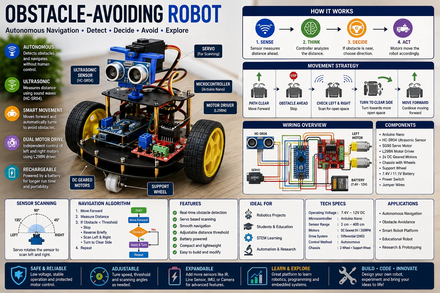
Project Overview
The robot continuously measures the distance to objects in front of it. When an obstacle is detected within a selected distance, the controller stops the motors and selects another direction.
Distance Sensor
       │
       ▼
Microcontroller
       │
       ▼
Navigation Logic
       │
       ▼
Motor Driver
       │
   ┌───┴───┐
   ▼       ▼
Left     Right
Motor    Motor
This simple feedback system allows the robot to move autonomously around obstacles.
Robot Platform
A basic two-wheel robot can be constructed using two geared DC motors, two wheels and a free-moving caster or skid.
        FRONT
          ▲
          │
    ┌─────────────┐
    │   SENSOR    │
    │             │
    │             │
    │             │
    │             │
    └─────────────┘
      O         O
    LEFT      RIGHT
    MOTOR     MOTOR
The two motors can be controlled independently, allowing the robot to move forward, reverse and turn.
Ultrasonic Distance Sensor
An ultrasonic sensor measures distance by transmitting a sound pulse above the normal range of human hearing and measuring the time taken for the reflected pulse to return.
Sensor
  │
  │  Ultrasonic Pulse
  ▼
Object
  │
  │  Echo
  ▼
Sensor
The controller can calculate distance from the measured echo time.
Distance Measurement
The basic relationship is:
Distance = Time × Speed of Sound / 2
The division by two is required because the ultrasonic pulse travels from the sensor to the object and then back to the sensor.
The speed of sound varies with environmental conditions, particularly temperature, so the calculated distance is an approximation unless environmental compensation is applied.
Obstacle Detection
The controller compares the measured distance with a predefined obstacle threshold.
Measure Distance
       │
       ▼
Distance < Threshold?
    ┌──┴──┐
   YES    NO
    │      │
    ▼      ▼
 Stop    Forward
Robot    Motion
For example, the robot could begin its avoidance routine when an obstacle is detected within a selected distance.
Microcontroller
An Arduino-compatible controller, ESP32 or another suitable microcontroller can control the robot.
The controller handles:
- Distance measurement.
- Obstacle detection.
- Motor control.
- Direction selection.
- Timing.
- Navigation logic.
Motor Driver
The microcontroller cannot normally provide enough current to drive the DC motors directly.
A motor-driver circuit is therefore used between the controller and motors.
Microcontroller
      │
      ▼
 Motor Driver
   │       │
   ▼       ▼
Left     Right
Motor    Motor
The driver should be selected according to the motor voltage and stall-current requirements.
H-Bridge Motor Control
An H-bridge allows the direction of a DC motor to be reversed.
         +V
          │
      ┌───┴───┐
      │ H-BRIDGE
      └───┬───┘
          │
        MOTOR
          │
         GND
By changing the switching states, the controller can make the motor rotate forward or backward.
Basic Motor Commands
A two-wheel robot can produce several useful movements.
Left Motor   Right Motor

Forward       Forward       → Forward

Reverse       Reverse       → Reverse

Forward       Stop          → Turn Right

Stop          Forward       → Turn Left

Reverse       Forward       → Rotate
The exact direction depends on the mechanical arrangement and motor wiring.
Forward Motion
During normal operation, both motors rotate in the forward direction.
      FRONT
        ↑

   ↺         ↻
 LEFT      RIGHT
 MOTOR     MOTOR

        → → →


The robot continuously checks the distance sensor while moving.
Obstacle Avoidance
When an obstacle is detected, the robot can stop and determine which direction has more available space.
Obstacle Detected │ ▼ STOP │ ▼ Measure Left │ ▼ Measure Right │ ▼ Choose Clearer Direction │ ▼ TURN │ ▼ Continue
Scanning Left and Right
A servo motor can rotate the ultrasonic sensor to inspect different directions.
Sensor │ ┌────┴────┐ │ SERVO │ └────┬────┘ │ LEFT ← ● → RIGHT
The controller can measure the distance on the left and right before selecting the preferred direction.
Servo-Controlled Sensor
A small servo can rotate the sensor through a range of angles.
For example:
90° │ ▼ FRONT 45° 135° │ │ ▼ ▼ LEFT RIGHT
The controller can compare the measured distances and turn toward the direction with more free space.
Simple Avoidance Algorithm
A basic algorithm can operate as follows:
Start │ ▼ Move Forward │ ▼ Measure Distance │ ▼ Obstacle? ┌┴───────┐ NO YES │ │ ▼ ▼ Forward Stop │ ▼ Reverse Briefly │ ▼ Scan Directions │ ▼ Choose Direction │ ▼ Turn │ └────► Forward
Reverse Before Turning
If the robot is very close to an obstacle, it may first reverse for a short period before turning.
This provides additional space for the robot to rotate.
Obstacle ████████████ ↑ │ Robot │ ▼ Reverse │ ▼ Turn │ ▼ Continue
Turning Strategy
The robot can use several strategies when an obstacle is detected.
- Always turn left.
- Always turn right.
- Choose the side with greater distance.
- Alternate directions.
- Use a predefined navigation pattern.
Choosing the direction with more free space generally provides more flexible behavior than always turning in the same direction.
Motor Speed Control
PWM can be used to control motor speed.
PWM Low │ ▼ Slow Motor PWM Medium │ ▼ Medium Speed PWM High │ ▼ High Speed
The motor-driver and motor must both be capable of operating with the chosen PWM method.
Differential Steering
The robot can turn by running the two motors at different speeds.
Left Motor = 50% Right Motor = 100% ↓ Robot curves left
This allows smoother steering than simply stopping one motor.
Pivot Turning
A sharper turn can be achieved by running one motor forward and the other backward.
Left Motor Reverse Right Motor Forward ↓ Robot rotates
This is useful when the robot needs to turn within a small area.
Battery Supply
The robot requires a battery capable of supplying both the motors and control electronics.
Motor current can vary significantly, especially during acceleration and when the wheels are obstructed.
The battery and wiring should therefore be selected according to the motor's actual current requirements.
Separate Logic Supply
Motor noise and voltage fluctuations can interfere with the microcontroller.
The design can use appropriate regulation and decoupling for the logic supply.
Battery │ ├────► Motor Driver ───► Motors │ └────► Regulator ──────► Microcontroller
The grounds must be connected appropriately for the chosen driver and control architecture.
Motor Noise
Brushed DC motors can generate electrical noise through their brushes and commutators.
Suitable suppression, wiring, decoupling and PCB layout can reduce the effect of this noise on the controller.
Sensor Blind Spots
An ultrasonic sensor does not provide perfect coverage of the area around the robot.
Very small objects, angled surfaces and objects outside the sensor's effective field can be difficult to detect.
A sensor mounted on a servo can improve coverage by scanning multiple directions.
Multiple Sensors
More advanced robots can use multiple distance sensors.
FRONT ┌─────┬─────┐ │ L │ R │ │Sensor Sensor └─────┬─────┘ │ Robot
Multiple sensors can reduce blind spots and allow faster obstacle detection.
Infrared Distance Sensors
Infrared distance sensors can also be used for obstacle detection.
They can be useful at short distances and can complement ultrasonic sensors.
The choice depends on the required range, object characteristics and environment.
Navigation State Machine
A state machine makes the robot's behavior easier to organize.
FORWARD │ ▼ OBSTACLE │ ▼ REVERSE │ ▼ SCAN │ ▼ TURN │ └────► FORWARD
Each state performs a specific action before transitioning to another state.
Stuck Detection
A robot can sometimes become trapped between obstacles.
The software can detect repeated unsuccessful movements and initiate an escape routine.
Repeated Obstacle │ ▼ Change Strategy │ ▼ Reverse Longer │ ▼ Rotate │ ▼ Search Again
Wheel Slip
Motor commands do not always correspond directly to actual movement.
Wheel slip can occur on smooth, dusty or uneven surfaces.
For simple obstacle avoidance this is generally acceptable because the robot relies primarily on distance sensing rather than precise position tracking.
Encoders
Wheel encoders can provide feedback about motor rotation.
Wheel │ ▼ Encoder │ ▼ Pulse Count │ ▼ Microcontroller │ ▼ Movement Feedback
Encoders allow more advanced control of speed, distance and turning angle.
Improving Navigation
The basic obstacle-avoidance algorithm can be expanded with:
- Wheel encoders.
- Multiple distance sensors.
- Servo scanning.
- Speed control.
- Gyroscope or IMU.
- Mapping.
- Path planning.
These additions can turn the simple robot into a more sophisticated autonomous platform.
Testing the Robot
- Inspect the mechanical assembly.
- Check wheel alignment.
- Verify motor wiring.
- Verify battery voltage.
- Test each motor independently.
- Test the motor driver.
- Test the distance sensor.
- Verify distance readings.
- Test forward movement.
- Test reverse movement.
- Test left and right turns.
- Test obstacle detection.
- Test the complete avoidance routine.
- Test the robot on different surfaces.
Troubleshooting
Robot Does Not Move
- Check the battery.
- Check motor-driver supply.
- Check motor wiring.
- Check motor-driver enable signals.
- Check the controller outputs.
One Motor Runs Backwards
- Reverse the motor's two wires.
- Alternatively invert its direction in software.
Distance Sensor Gives Incorrect Readings
- Check sensor wiring.
- Check the trigger and echo signals.
- Check supply voltage.
- Check sensor alignment.
- Check the object's surface.
Robot Keeps Turning
- Check the distance threshold.
- Check sensor readings.
- Check motor direction.
- Check the navigation state machine.
- Check whether the robot is trapped.
Microcontroller Resets
- Check battery voltage.
- Check motor startup current.
- Improve power decoupling.
- Separate motor and logic power paths where appropriate.
- Check motor noise.
Common Mistakes
- Driving motors directly from microcontroller GPIO pins.
- Using an undersized motor driver.
- Ignoring motor stall current.
- Using a weak battery.
- Failing to provide adequate controller decoupling.
- Using an unsuitable obstacle threshold.
- Ignoring sensor blind spots.
- Failing to handle situations where the robot becomes trapped.
- Testing at full speed before verifying the control system.
Applications
- Educational robotics.
- Autonomous vehicle experiments.
- Robotics competitions.
- Microcontroller projects.
- Sensor experiments.
- Motor-control experiments.
- Autonomous navigation research.
Safety Notes
- Use a battery appropriate for the motor system.
- Protect exposed battery terminals.
- Keep fingers and loose objects away from moving wheels.
- Do not operate the robot near stairs or dangerous drop-offs.
- Secure wiring so it cannot contact moving parts.
- Use appropriate protection for rechargeable batteries.
- Disconnect the battery before servicing the electronics.
Skills Learned
- Ultrasonic distance measurement.
- Obstacle detection.
- DC motor control.
- H-bridge operation.
- PWM speed control.
- Differential steering.
- Servo control.
- Autonomous navigation.
- State-machine programming.
- Robotics troubleshooting.
Key Points
- An obstacle-avoiding robot uses sensors to detect objects without human intervention.
- Ultrasonic sensors can provide useful distance measurements.
- A motor driver is required to control DC motors safely from a microcontroller.
- Two independently controlled motors allow differential steering.
- A servo can rotate a sensor to inspect different directions.
- Hysteresis and appropriate distance thresholds can improve stable behavior.
- A state machine makes autonomous navigation logic easier to manage.
- Encoders and additional sensors can significantly improve navigation.
- Motor power requirements must account for startup and stall current.
- Good power and wiring design helps prevent controller resets caused by motor noise.