
Programmable Power Supply
Build a versatile programmable DC bench power supply with adjustable voltage, adjustable current limiting, digital monitoring and stored operating presets.
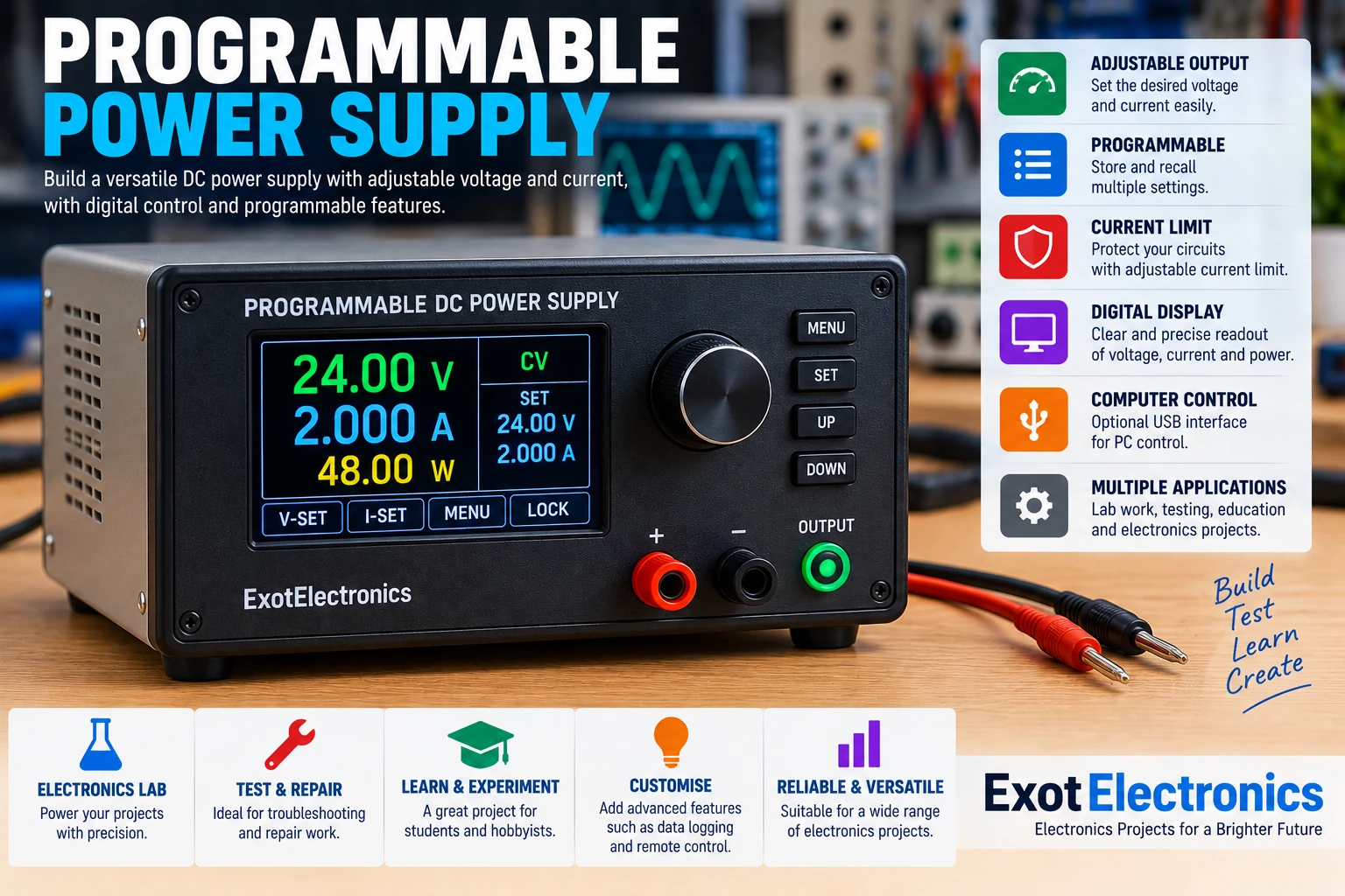
What Is a Programmable Power Supply?
A programmable power supply is a regulated DC power source whose output voltage and current limit can be controlled electronically. Instead of relying entirely on front-panel potentiometers, the settings can be selected digitally and, in more advanced designs, controlled by a microcontroller or computer.
This makes the supply useful for electronics development, testing, troubleshooting, repair and automated experiments.
Why Build One?
A programmable supply combines the flexibility of a conventional bench supply with digital control. Once the basic regulator is working, many useful features can be added around it.
- Digitally adjustable output voltage.
- Adjustable current limiting.
- Digital voltage and current measurement.
- Programmable output presets.
- Output enable and disable control.
- Over-current protection.
- Over-voltage protection.
- Optional computer or remote control.
Basic Architecture
The power supply can be divided into several functional sections. The input stage provides the raw DC voltage, the regulator controls the output, and a measurement and control system supervises the supply.
Adjustable Voltage
The voltage control determines the desired output voltage. In a digitally controlled design, a microcontroller can generate a control value that is converted into an analog reference for the regulator.
The actual output voltage should also be measured independently and fed back to the controller. This allows the software to display the actual output and detect abnormal conditions.
Constant-Voltage Operation
In constant-voltage operation, the supply attempts to maintain the programmed output voltage while the load current remains below the configured current limit.
For example, the user could select a voltage suitable for powering a circuit while setting a conservative current limit to protect the circuit during initial testing.
Current Limiting
Current limiting is one of the most important features of a bench power supply. A current-sense circuit measures the output current and allows the regulator to reduce its output when the programmed limit is reached.
This is especially useful when powering an unknown or newly constructed circuit. A low current limit can prevent a wiring mistake from causing excessive current.
Constant-Current Operation
When a load attempts to draw more current than the programmed limit, the supply can transition from constant-voltage operation toward current-limited operation.
The display can indicate that the current limit has been reached. This provides useful information during circuit testing and troubleshooting.
Digital Measurement
A programmable supply normally measures both output voltage and output current. These measurements can be displayed locally and can also be used by the controller for protection and regulation.
| Measurement | Purpose |
|---|---|
| Output voltage | Displays the actual DC output |
| Output current | Shows load consumption |
| Power | Optional calculated voltage × current value |
| Temperature | Optional thermal protection |
Microcontroller
A microcontroller can provide the user interface, measurements, protection logic and programmable features. Suitable devices include common microcontrollers with ADC inputs and digital interfaces.
The controller does not necessarily have to carry the main regulator current. Keeping the control electronics separate from the power stage makes the design easier to manage and protect.
Digital-to-Analog Control
If the regulator requires an analog control voltage, the microcontroller can use a DAC or an appropriately filtered PWM signal to create the required reference.
The control resolution determines how finely the output voltage and current can be adjusted. Filtering and careful grounding are important when using PWM as an analog control source.
Presets
One advantage of programmable control is the ability to store frequently used voltage and current settings.
- Save commonly used voltage settings.
- Save corresponding current limits.
- Recall settings quickly during testing.
- Use different presets for different projects.
Output Enable
An output-enable function allows the user to configure the supply before applying power to the circuit under test.
This is useful because voltage and current settings can be checked on the display before the output is connected to the load.
Protection Features
A practical programmable supply should include appropriate protection mechanisms for both the power stage and the load.
- Over-current protection.
- Current limiting.
- Over-voltage detection.
- Over-temperature protection.
- Input protection.
- Short-circuit protection.
- Output shutdown on serious faults.
Thermal Management
Power regulators can dissipate significant heat when the input voltage is considerably higher than the output voltage or when the load current is high.
A heatsink, forced-air cooling or a more efficient switching regulator may therefore be required depending on the intended output power.
A temperature sensor can be added to the heatsink and used by the controller to reduce the output or shut the supply down if excessive temperature is detected.
Linear vs Switching Regulation
| Linear Regulator | Switching Regulator |
|---|---|
| Low output noise is possible | High efficiency is possible |
| Simple control | More complex circuitry |
| More heat at large voltage drops | Usually less heat |
| Good for low-noise applications | Good for higher-power applications |
A hybrid design can also be used, combining a switching pre-regulator with a linear post-regulator where low noise is important.
Typical Control Range
The actual voltage and current range depends on the power stage selected for the project. A laboratory supply might be designed around a low-voltage DC range suitable for electronics development.
| Parameter | Example Design Range |
|---|---|
| Output voltage | 0–30 V DC |
| Output current | 0–5 A |
| Voltage adjustment | Digital |
| Current adjustment | Digital |
| Display | Digital voltage/current display |
These are example project values rather than fixed specifications. The regulator, transformer or switching stage, heatsink and enclosure should all be selected for the intended output power.
Computer Control
An optional USB, serial or network interface can allow a computer to configure the supply and retrieve measurements.
Computer control can be useful for automated testing, production test fixtures, data logging and experiments where the output needs to change according to a programmed sequence.
Data Logging
The controller can periodically record output voltage, current and other measurements. The resulting data can be used to investigate a circuit's behavior over time.
Logging can also help identify intermittent faults, thermal problems and unusual changes in current consumption.
Typical Components
| Part | Function |
|---|---|
| DC input source | Provides raw DC power |
| Power regulator | Controls the output voltage |
| Current-sense resistor | Measures output current |
| Microcontroller | Provides digital control and monitoring |
| ADC / measurement circuit | Measures voltage and current |
| DAC or PWM filter | Generates analog control signals |
| Display | Shows settings and measurements |
| Encoder/buttons | User controls |
| Cooling system | Removes heat from the power stage |
Testing the Supply
- Check all wiring before applying power.
- Power the control electronics first where possible.
- Verify the displayed measurements.
- Set a low voltage and conservative current limit.
- Connect a suitable test load.
- Increase voltage gradually.
- Check regulation and current limiting.
- Monitor temperature at higher loads.
Testing With an Electronic Load
An electronic load provides a convenient way to test the power supply without risking an experimental circuit.
Load current can be increased progressively while monitoring the output voltage, current and temperature. This helps determine whether the supply can maintain regulation at the intended operating point.
Troubleshooting
Output voltage is incorrect
Check the voltage-sense wiring, reference voltage, DAC or PWM control signal and measurement calibration. Confirm the regulator is operating within its intended range.
Current reading is incorrect
Check the current-sense resistor, amplifier gain, ADC reference and calibration values. Verify the sense resistor has an appropriate rating.
Supply enters current limit too early
Check the programmed limit and current measurement circuit. Also inspect the wiring and output terminals for excessive resistance or an unexpected load.
Output is unstable
Check regulator compensation, output capacitance, wiring, grounding and control-loop behavior. Digital control should not introduce excessive noise into the analog regulation loop.
Power stage becomes too hot
Check the voltage drop across the regulator and the load current. Improve heatsinking or cooling, reduce the input-output voltage difference, or consider a more efficient switching pre-regulator.
Construction Tips
- Keep high-current wiring short and adequately sized.
- Separate power and measurement wiring.
- Use star or carefully planned grounding.
- Place decoupling capacitors close to control ICs.
- Keep switching nodes away from sensitive analog measurement circuits.
- Provide adequate ventilation around heatsinks.
- Clearly label voltage, current and output controls.
Practical Applications
- Powering microcontroller projects.
- Testing analog circuits.
- Testing audio amplifiers.
- Repairing electronic equipment.
- Battery and charging experiments.
- Development of sensors and embedded systems.
- Automated electronics testing.
- Educational laboratory experiments.
Safety
A bench power supply can deliver enough current to damage components, wiring and circuit boards. Always select an appropriate current limit before powering an unknown circuit.
If the supply contains a mains-powered input stage, the mains section must be physically separated from the low-voltage electronics and enclosed appropriately. Use suitable fusing, earthing, insulation and strain relief.
Never work on exposed mains circuitry while it is energized.