
Build a Pure Sine Wave Inverter
A pure sine wave inverter converts DC power from a battery or other DC source into AC power with a waveform that closely resembles the utility mains waveform. This project introduces SPWM generation, MOSFET H-bridge switching, transformer operation, output filtering, feedback regulation and protection circuits used in high-power inverters.
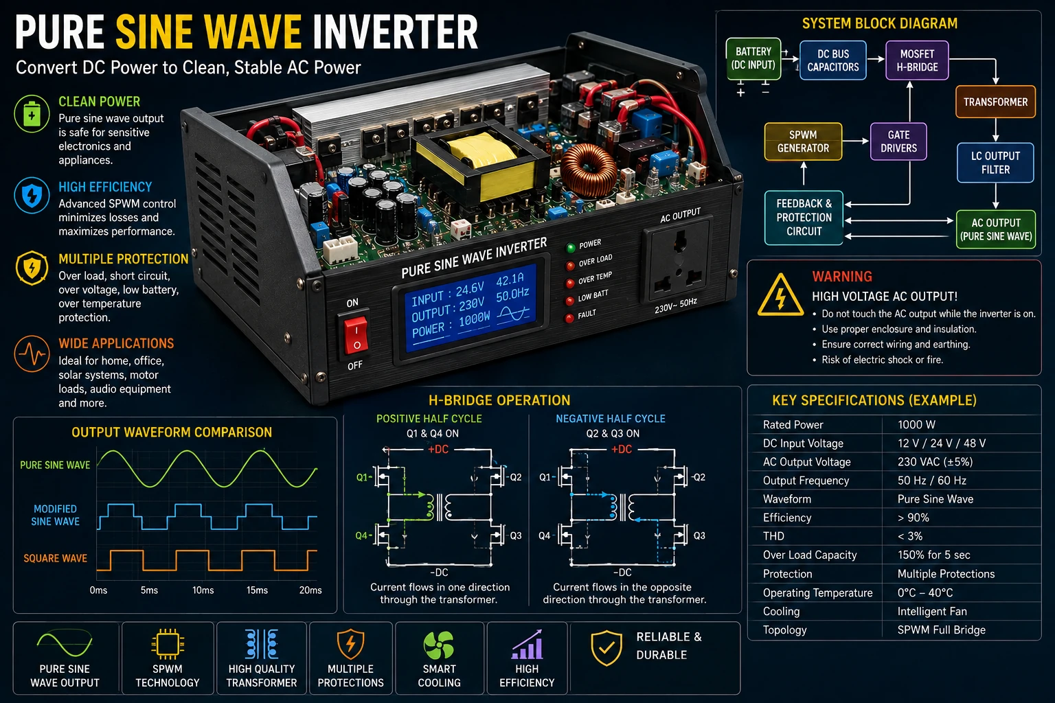
Project Overview
A typical inverter starts with a low-voltage DC source such as a battery. Electronic switching devices then convert this DC energy into a high-frequency or low-frequency AC waveform.
In a pure sine wave inverter, the switching waveform is controlled so that the final filtered output closely follows a sinusoidal waveform.
Battery
   │
   ▼
DC Input
   │
   ▼
MOSFET H-Bridge
   │
   ▼
SPWM Waveform
   │
   ▼
Transformer
   │
   ▼
LC Output Filter
   │
   ▼
Pure Sine Wave AC
Why Pure Sine Wave?
Many inexpensive inverters produce a square wave or modified waveform. A pure sine wave inverter provides a much smoother AC waveform.
This is useful for equipment such as:
- Audio equipment.
- Transformers.
- Motors.
- Fans.
- Computers.
- Power supplies.
- Electronic instruments.
The exact compatibility of any load depends on the inverter design and the equipment being powered.
Basic Inverter Architecture
        DC Battery
            │
            ▼
      Input Protection
            │
            ▼
       DC Bus Capacitor
            │
            ▼
       MOSFET H-Bridge
            │
            ▼
      Switching Waveform
            │
            ▼
        Transformer
            │
            ▼
      Secondary Rectification
            │
            ▼
        LC Filtering
            │
            ▼
        AC Output
The exact topology depends on whether the inverter uses a low-frequency transformer, a high-frequency conversion stage, or a combination of both.
Battery Input
The battery supplies the DC energy required by the inverter.
Common battery systems include 12 V, 24 V and 48 V configurations.
Higher battery voltages reduce the current required for a given output power.
P = V × I
For example, an inverter delivering 500 W from a 12 V battery would require substantially more input current than the same inverter operating from a 48 V battery.
Battery Current
The approximate DC input current can be estimated from:
I = P / V
The real current will be higher because the inverter is not 100% efficient.
For example, for a 500 W inverter operating at 90% efficiency from a 12 V battery:
Input Power = 500 / 0.90

Input Power ≈ 556 W

Current ≈ 556 / 12

Current ≈ 46 A
This illustrates why high-power low-voltage inverters require very thick wiring, suitable connectors and careful thermal design.
Input Protection
The battery input should include appropriate protection.
- Fuse or circuit breaker.
- Reverse-polarity protection where appropriate.
- Input filtering.
- Over-current protection.
- Low-battery protection.
- Suitable DC wiring.
The fuse should be located close to the battery connection so that the cable itself is protected against a short circuit.
DC Bus Capacitors
Large capacitors are normally placed close to the switching stage.
They provide a local energy reservoir and reduce voltage fluctuations caused by rapidly changing switching currents.
The capacitors must have suitable voltage, ripple-current and temperature ratings.
MOSFET H-Bridge
A full bridge, commonly called an H-bridge, can reverse the polarity applied to the transformer primary.
             DC+
              │
          ┌───┴───┐
          │       │
         Q1       Q2
          │       │
          ├───┬───┤
              │
          Transformer
              │
          ├───┴───┤
          │       │
         Q3       Q4
          │       │
          └───┬───┘
              │
             GND
The switches are controlled in complementary groups so that current flows through the transformer in alternating directions.
H-Bridge Operation
During one half-cycle, one diagonal pair of MOSFETs conducts.
Q1 + Q4 ON

Current flows in one direction
through the transformer.
During the opposite half-cycle, the other diagonal pair conducts.
Q2 + Q3 ON

Current flows in the opposite
direction.
Alternating the polarity creates an AC waveform at the transformer.
SPWM Generation
Pure sine wave inverters commonly use sinusoidal pulse-width modulation, or SPWM.
Instead of simply switching the bridge between two states at the output frequency, the switching pulse widths are continuously varied according to a sine-wave reference.
Sine Reference
       │
       ▼
Comparator
       ▲
       │
Triangle Carrier
       │
       ▼
     SPWM
       │
       ▼
   MOSFET Bridge
The resulting high-frequency pulse train contains information corresponding to the desired sine wave.
Sine Reference
The reference waveform represents the desired output sine wave.
For a 50 Hz inverter, the reference waveform completes 50 cycles per second.
For a 60 Hz inverter, it completes 60 cycles per second.
The reference frequency should match the intended AC output frequency.
Carrier Frequency
The SPWM reference is compared with a higher-frequency carrier.
The carrier may operate at several kilohertz or higher depending on the switching devices, transformer and filtering requirements.
Higher switching frequency can simplify filtering but generally increases switching losses.
Modulation Index
The modulation index controls the amplitude of the generated fundamental waveform.
Changing the modulation index changes the effective AC output voltage.
The controller should keep the modulation within the safe operating range of the chosen PWM scheme.
Gate Drivers
The MOSFET gates require suitable drive signals.
A gate-driver circuit provides the required voltage and current to charge and discharge the MOSFET gates quickly.
PWM Controller
      │
      ▼
Gate Driver
      │
      ├────► High-Side MOSFET
      │
      └────► Low-Side MOSFET
The exact driver arrangement depends on the bridge topology and the MOSFET gate-drive requirements.
Dead Time
Dead time is required between switching one device off and turning its opposite device on.
High Side:

──────ON──────OFF────────ON──────

Low Side:

──────────ON──────OFF────────ON──
             ↑
          Dead Time
Without adequate dead time, both devices in one bridge leg could conduct simultaneously, creating shoot-through current.
Transformer
The transformer can increase the voltage from the low-voltage switching stage to the required AC output voltage.
Transformer design depends on:
- Input voltage.
- Output voltage.
- Power rating.
- Operating frequency.
- Core material.
- Turns ratio.
- Winding arrangement.
- Insulation.
- Cooling.
Transformer Turns Ratio
The approximate voltage relationship is determined by the turns ratio:
Np / Ns ≈ Vp / Vs
In an actual inverter, switching waveform, losses, regulation and operating conditions must also be considered.
Output LC Filter
The SPWM waveform contains a fundamental component and high-frequency switching components.
An LC filter removes much of the high-frequency switching energy.
SPWM
 │
 ▼
Inductor
 │
 ├──── Capacitor ──── GND
 │
 ▼
Filtered AC
The filter is designed so that the desired AC frequency passes while the switching-frequency components are strongly attenuated.
Filter Cutoff Frequency
For an ideal simple LC network, the approximate resonant frequency is:
fc = 1 / (2π√LC)
The practical filter must also consider load impedance, damping, component losses and inverter control behavior.
Output Voltage Feedback
A feedback circuit can monitor the AC output and adjust the SPWM modulation to maintain the desired voltage.
AC Output
   │
   ▼
Voltage Sensor
   │
   ▼
Controller
   │
   ▼
SPWM
   │
   ▼
MOSFET Bridge
   │
   └────────────► Transformer
Feedback helps compensate for changes in battery voltage and load.
Low-Battery Protection
A battery should not be discharged below its appropriate safe voltage.
The controller can monitor the battery voltage and reduce or disable the inverter when the voltage becomes too low.
The correct cutoff voltage depends on the battery chemistry and system design.
Over-Current Protection
A current-sensing circuit can monitor the current through the DC input or switching bridge.
If excessive current is detected, the controller can reduce the PWM level or shut down the inverter.
Hardware current protection is preferable to relying exclusively on software.
Short-Circuit Protection
A short circuit at the AC output can produce very high current.
The inverter should therefore have a suitable protection mechanism.
Possible protection methods include current sensing, electronic shutdown and an appropriately rated output circuit breaker or fuse.
Over-Temperature Protection
MOSFETs, transformers, inductors and other components generate heat.
Temperature sensors can be used to monitor heatsinks or other critical components.
Temperature Sensor
       │
       ▼
Controller
       │
       ├──► Fan Control
       │
       └──► Shutdown
Cooling
High-power inverters commonly require forced-air cooling.
The heatsink must be capable of transferring the semiconductor losses to the surrounding air without allowing the junction temperature to exceed its safe limit.
Thermal interface material and proper mounting are also important.
Efficiency
Inverter efficiency can be estimated using:
Efficiency =
Output Power / Input Power × 100%
For example, a 1000 W inverter operating at 90% efficiency requires approximately:
Input Power = 1000 / 0.90

Input Power ≈ 1111 W
Approximately 111 W is therefore lost as heat.
MOSFET Selection
The switching MOSFETs should be selected according to the actual voltage, current and switching conditions.
Important parameters include:
- Drain-source voltage rating.
- Continuous current rating.
- Pulse current capability.
- RDS(on).
- Total gate charge.
- Switching characteristics.
- Thermal resistance.
The MOSFET voltage rating should include sufficient margin above the actual switching voltage.
PCB Layout
High-current switching paths should be kept short and low impedance.
- Use adequate copper width.
- Keep gate-drive paths short.
- Place DC-link capacitors close to the bridge.
- Minimize switching-loop area.
- Separate power and control grounds appropriately.
- Keep feedback wiring away from noisy switching nodes.
- Provide adequate creepage and clearance.
Battery Wiring
At high power, battery currents can become very large.
The cables must therefore have adequate current capacity and low voltage drop.
Loose battery connections can become extremely hot and can create a serious fire hazard.
Output Protection
The AC output should have appropriate protection for the intended application.
- Output fuse or circuit breaker.
- Suitable enclosure.
- Protected output terminals.
- Appropriate earthing arrangements where applicable.
- Over-current protection.
Testing the Inverter
A high-power inverter should never be tested immediately at full load.
- Inspect the complete circuit.
- Check MOSFET orientation.
- Check gate-driver connections.
- Check dead time.
- Verify the control supply.
- Verify the PWM waveform.
- Test the bridge at low voltage where practical.
- Check the transformer connections.
- Test with a small load.
- Increase the load gradually.
- Monitor temperature and current.
- Verify output waveform and voltage.
Oscilloscope Measurements
An oscilloscope is useful for examining:
- Gate-drive signals.
- Dead time.
- H-bridge switching waveforms.
- SPWM waveform.
- Transformer primary waveform.
- Output waveform.
- Switching spikes.
Measurements on the high-voltage output require properly rated probes and suitable isolation procedures.
Checking the Output Waveform
The final output should be examined with an oscilloscope and, where available, suitable power-quality measurement equipment.
A correctly designed filter should substantially reduce the high-frequency PWM components while retaining the desired AC fundamental.
Troubleshooting
No AC Output
- Check the battery voltage.
- Check the controller supply.
- Check PWM generation.
- Check gate-driver operation.
- Check MOSFETs.
- Check transformer wiring.
- Check protection circuits.
MOSFETs Become Very Hot
- Check gate-drive voltage.
- Check switching timing.
- Check dead time.
- Check switching frequency.
- Check MOSFET RDS(on).
- Improve heatsinking.
- Check for shoot-through.
Output Voltage Is Too Low
- Check battery voltage.
- Check modulation index.
- Check transformer turns ratio.
- Check output filter.
- Check voltage feedback.
- Check excessive loading.
Output Waveform Is Distorted
- Check SPWM generation.
- Check dead time.
- Check transformer saturation.
- Check output filter design.
- Check excessive loading.
- Check DC offset.
Inverter Shuts Down Under Load
- Check over-current protection.
- Check battery voltage drop.
- Check MOSFET temperature.
- Check transformer temperature.
- Check battery and cable capacity.
Common Mistakes
- Using insufficiently rated MOSFETs.
- Ignoring dead time.
- Using inadequate battery wiring.
- Undersizing the heatsinks.
- Ignoring transformer losses.
- Using an unsuitable output filter.
- Testing directly at full power.
- Relying only on software protection.
- Ignoring battery voltage drop under load.
- Failing to provide proper AC output protection.
Safety Notes
- The inverter output can be lethal.
- Never touch the AC output while energized.
- Use a properly insulated enclosure.
- Use appropriate fuses and circuit breakers.
- Keep high-voltage wiring separated from low-voltage control wiring.
- Maintain appropriate creepage and clearance.
- Use properly rated measurement equipment.
- High-current batteries can deliver enormous short-circuit currents.
- Protect battery wiring with an appropriately rated fuse.
- Do not work on an energized inverter.
Skills Learned
- DC-to-AC power conversion.
- SPWM generation.
- MOSFET H-bridge operation.
- Gate-driver design.
- Transformer operation.
- LC filtering.
- Voltage feedback.
- Current sensing.
- Thermal management.
- High-power inverter testing.
Key Points
- A pure sine wave inverter converts DC power into a controlled AC waveform.
- SPWM can be used to approximate a sine wave before filtering.
- An H-bridge can reverse the polarity applied to the transformer.
- Gate drivers provide suitable switching signals to the MOSFETs.
- Dead time helps prevent shoot-through.
- An LC filter removes much of the high-frequency switching content.
- Feedback can regulate the AC output voltage.
- Current, temperature and battery-voltage protection are essential.
- High-power low-voltage inverters can draw very large battery currents.
- The AC output must be treated as potentially lethal.