
Build a 500 W SMPS Power Supply
A high-power switch-mode power supply can deliver hundreds of watts from a relatively compact transformer and heatsink. This project explores the architecture of a 500 W SMPS, including mains rectification, high-frequency switching, transformer isolation, secondary rectification, filtering, feedback and protection.
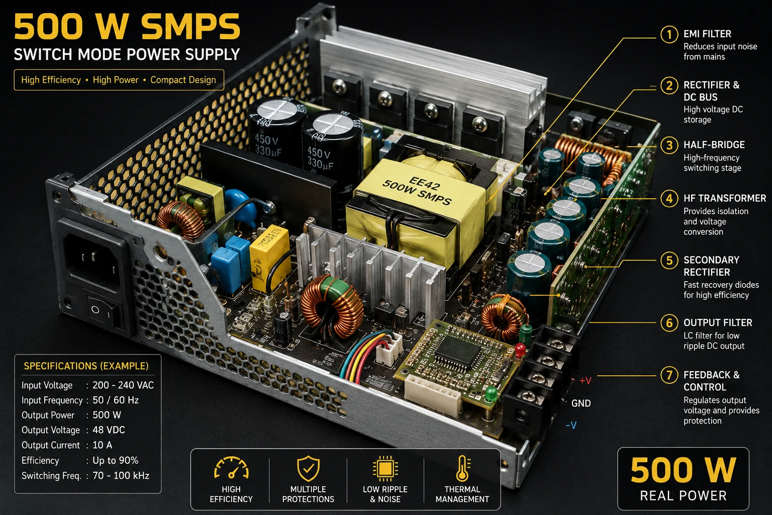
Project Overview
A conventional linear power supply uses a transformer operating at the mains frequency. At several hundred watts, that transformer can become large and heavy.
A switch-mode power supply solves this problem by converting the input into high-frequency electrical energy before applying it to a much smaller high-frequency transformer.
AC Input
   │
   ▼
Rectifier
   │
   ▼
DC Bus
   │
   ▼
High-Frequency Switching
   │
   ▼
HF Transformer
   │
   ▼
Secondary Rectifier
   │
   ▼
Output Filter
   │
   ▼
DC Output
Why Use an SMPS?
- Much smaller transformer than a mains-frequency design.
- High power density.
- High efficiency when properly designed.
- Reduced heatsink requirements.
- Wide input-voltage capability can be possible.
- Suitable for high-power amplifier supplies.
The increased complexity of an SMPS requires considerably more careful design than a conventional linear power supply.
Typical 500 W Architecture
AC Mains
   │
   ▼
Fuse / Protection
   │
   ▼
EMI Filter
   │
   ▼
Bridge Rectifier
   │
   ▼
Bulk Capacitors
   │
   ▼
Half-Bridge Switching Stage
   │
   ▼
High-Frequency Transformer
   │
   ▼
Fast Secondary Rectifier
   │
   ▼
LC Output Filter
   │
   ▼
DC Output
A feedback circuit monitors the output and adjusts the switching operation to maintain regulation.
Input Rectifier
The AC input is first converted into high-voltage DC using a bridge rectifier and bulk capacitors.
The resulting DC bus is then switched at a much higher frequency than the original mains frequency.
The exact DC-bus voltage depends on the AC input and the rectifier configuration.
Bulk Capacitors
Large electrolytic capacitors smooth the rectified input waveform and provide energy storage for the switching stage.
These capacitors must have suitable voltage, ripple-current and temperature ratings.
They can remain dangerously charged after the power supply has been disconnected.
Half-Bridge Switching Stage
A half-bridge is a practical topology for medium- to high-power SMPS designs.
             DC Bus
               │
              Q1
               │
               ├────► Transformer
               │
              Q2
               │
              GND
The switching devices alternately apply voltage to the transformer primary.
The switching frequency is much higher than mains frequency, allowing the transformer to be considerably smaller.
IR2153 Controller
The IR2153 is a self-oscillating half-bridge driver that can simplify the control of a basic half-bridge converter.
It provides complementary gate-drive signals suitable for controlling the two switching devices in a half-bridge arrangement.
The switching frequency is determined by the timing components connected to the controller.
Gate Drive
The MOSFET gates must be driven correctly to ensure reliable switching.
The high-side device requires a gate-drive arrangement that allows its gate voltage to move appropriately with the switching node.
Gate resistors can be used to control switching speed and reduce ringing.
The exact gate-drive network should follow the controller and MOSFET manufacturer recommendations.
Dead Time
The two half-bridge switches must not be fully on at the same time.
A suitable non-overlap period, commonly called dead time, prevents shoot-through current through the DC bus.
Q1:  ───────ON──────       ─────ON──────

Q2:       ───────ON──────       ─────ON────
             ↑
          Dead Time
Incorrect gate timing can cause extremely high current and destroy the switching devices.
High-Frequency Transformer
The transformer provides galvanic isolation and converts the switching waveform to the required output voltage.
Unlike a 50 Hz or 60 Hz transformer, the SMPS transformer operates at the switching frequency.
The core material, core size, winding arrangement, turns ratio, insulation and maximum flux density must all be considered carefully.
Transformer Turns Ratio
The turns ratio determines the approximate relationship between the primary and secondary voltages.
Np / Ns ≈ Vp / Vs
In a real converter, losses, switching waveform, duty cycle, leakage inductance and rectifier voltage drops must also be considered.
Transformer Core
Ferrite cores are commonly used for high-frequency power transformers.
The selected core must be capable of transferring the required power without excessive temperature rise or magnetic saturation.
Core selection should be based on the manufacturer's magnetic data rather than simply choosing a core by physical size.
Secondary Rectifier
The high-frequency transformer output is rectified using fast or appropriate power rectifiers.
Transformer Secondary
        │
        ▼
   Fast Rectifier
        │
        ▼
   LC Filter
        │
        ▼
      DC Out
The rectifier voltage and current ratings must be selected with appropriate safety margins.
Output Filter
The rectified switching waveform contains significant high-frequency components.
An LC filter reduces this switching ripple and produces a smoother DC output.
Rectifier
   │
   ▼
Inductor
   │
   ├──── Capacitor ──── GND
   │
   ▼
DC Output
Output Regulation
A practical 500 W supply requires feedback so that the output remains stable when the load or input voltage changes.
Output
  │
  ▼
Voltage Sense
  │
  ▼
Feedback Controller
  │
  ▼
PWM / Switching Control
  │
  ▼
Power Stage
  │
  └──────────────► Output
Isolated power supplies commonly use an optocoupler or another suitable isolated feedback method between the secondary and primary sides.
Soft Start
A high-power SMPS can draw substantial current during startup because the input capacitors must charge and the switching converter must establish normal operation.
A suitable startup arrangement can progressively establish operation and prevent excessive startup stress.
This is particularly important in high-power supplies.
Current Protection
A high-power converter should include current limiting or over-current protection.
The protection system can monitor primary current, secondary current or another suitable parameter.
If an abnormal current is detected, switching can be reduced or disabled.
Short-Circuit Protection
A short circuit at the output can cause extremely high current.
The converter should therefore be designed so that a short circuit does not immediately destroy the switching devices, transformer or rectifiers.
Protection may use cycle-by-cycle current limiting, shutdown, hiccup-mode operation or another appropriate method.
Over-Voltage Protection
An output over-voltage condition can damage equipment connected to the power supply.
A properly designed converter can detect excessive output voltage and disable the switching stage.
Thermal Protection
The switching MOSFETs, transformer, rectifiers and other components produce heat.
Temperature monitoring can be used to reduce the load or shut down the converter if temperatures become excessive.
Efficiency
SMPS efficiency is calculated as:
Efficiency = Output Power / Input Power × 100%
For a 500 W output and 90% efficiency:
Input Power = 500 / 0.90
Input Power ≈ 556 W
The remaining power is dissipated mainly as heat.
Switching Losses
The switching devices experience conduction and switching losses.
Switching losses generally increase as switching frequency and switching transition energy increase.
Good gate-drive design, appropriate switching devices and controlled switching transitions are therefore important.
Snubbers and Clamping
Transformer leakage inductance and parasitic capacitances can produce voltage spikes during switching.
Snubber or clamping networks may be required to control these spikes.
The correct values depend on the actual transformer, switching devices, layout and operating conditions and should be determined from measured waveforms.
PCB Layout
PCB layout is critical in a high-frequency power converter.
- Keep high-current switching loops compact.
- Minimize parasitic inductance.
- Keep gate-drive paths short.
- Separate noisy power paths from sensitive feedback circuits.
- Provide appropriate creepage and clearance.
- Use adequate copper width for high-current paths.
- Provide suitable thermal paths.
EMI Filtering
Fast switching edges can generate conducted and radiated electromagnetic interference.
An input EMI filter, appropriate layout and suitable shielding can reduce unwanted emissions.
The final filter design must be tested with the completed converter.
Testing
A high-power SMPS should not be tested immediately at full power.
- Inspect the PCB carefully.
- Verify component orientation.
- Check the gate-drive waveforms at low-risk conditions.
- Verify switching frequency.
- Check that the two switches operate correctly.
- Verify transformer connections.
- Test the secondary output at low load.
- Increase the load gradually.
- Monitor temperature and switching waveforms.
- Check output ripple and regulation.
Measuring Switching Waveforms
An oscilloscope is extremely useful when developing an SMPS.
Important waveforms include:
- MOSFET gate voltage.
- Half-bridge switching node.
- Primary transformer waveform.
- Secondary rectifier waveform.
- Output ripple.
- Current-sense waveform.
Measurements on the primary side of an offline mains-powered converter require appropriately rated and isolated test equipment.
Troubleshooting
No Output
- Check the control supply.
- Check switching frequency.
- Check MOSFET gate drive.
- Check transformer connections.
- Check secondary rectifiers.
- Check the output filter.
- Check the feedback circuit.
MOSFETs Fail Immediately
- Check for simultaneous conduction.
- Check gate-drive timing.
- Check transformer wiring.
- Check for excessive voltage spikes.
- Check snubber or clamp components.
- Check PCB layout.
Output Voltage Too High
- Check feedback polarity.
- Check the feedback divider.
- Check the optocoupler or feedback path.
- Check the control circuit.
Excessive Ripple
- Check output capacitors.
- Check output inductor.
- Check secondary rectifiers.
- Check switching frequency.
- Check PCB layout.
Transformer Overheats
- Check operating frequency.
- Check core selection.
- Check magnetic flux density.
- Check winding losses.
- Check transformer saturation.
- Check output power.
Common Mistakes
- Using an unsuitable transformer core.
- Incorrect transformer winding polarity.
- Insufficient creepage and clearance.
- Inadequate heatsinking.
- Ignoring switching spikes.
- Poor gate-drive layout.
- Insufficient output filtering.
- Operating without current protection.
- Testing immediately at full load.
Safety Notes
- This project can involve lethal mains voltage.
- The rectified primary DC bus can remain dangerously charged after power is removed.
- Use appropriate isolation, fusing and protective enclosures.
- Maintain adequate creepage and clearance.
- Never touch the primary circuit while energized.
- Use properly rated probes and measurement equipment.
- Discharge high-voltage capacitors safely before servicing.
- Keep the high-voltage primary and isolated secondary clearly separated.
- Use an appropriately rated transformer and insulation system.
Skills Learned
- Switch-mode power conversion.
- Half-bridge converters.
- High-frequency transformers.
- MOSFET gate driving.
- Output rectification.
- LC filtering.
- Feedback regulation.
- SMPS protection.
- Thermal management.
- High-frequency PCB layout.
Key Points
- An SMPS converts electrical energy at high frequency.
- High-frequency operation allows a smaller transformer.
- A half-bridge can be used for medium- and high-power conversion.
- The IR2153 can provide a simple half-bridge drive arrangement.
- The transformer provides isolation and voltage conversion.
- Fast secondary rectification and LC filtering produce the DC output.
- Feedback is required for regulated operation.
- Current, voltage and thermal protection are essential in a high-power converter.
- PCB layout has a major effect on switching performance and EMI.
- High-voltage SMPS development requires appropriate safety equipment and procedures.