
Build a Wi-Fi Smart Relay Controller
A Wi-Fi relay controller allows electrical loads to be switched remotely through a wireless network. This project uses an ESP32 microcontroller, a relay driver and a web-based control interface to create a practical smart switching system.
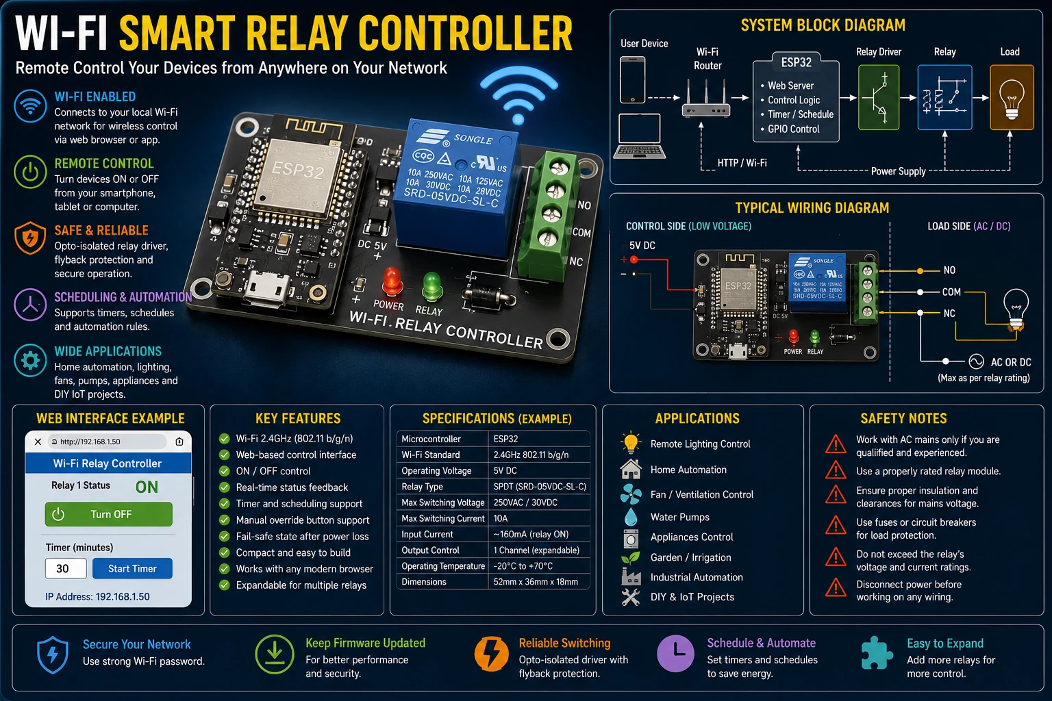
Project Overview
The controller connects to a Wi-Fi network and provides a way to control a relay remotely.
Smartphone / Computer
          │
          │ Wi-Fi
          ▼
      Wi-Fi Router
          │
          ▼
        ESP32
          │
          ▼
     GPIO Output
          │
          ▼
    Relay Driver
          │
          ▼
        Relay
          │
          ▼
         Load
The relay provides the switching interface between the low-voltage electronics and the controlled electrical load.
Why Use an ESP32?
The ESP32 combines a microcontroller with integrated Wi-Fi, making it well suited to small connected-control projects.
The controller can handle:
- Wi-Fi networking.
- Web-server operation.
- GPIO control.
- Relay switching.
- Status monitoring.
- User-interface handling.
- Automation logic.
Relay Module
A relay allows a low-voltage control circuit to switch a separate electrical circuit.
ESP32 GPIO
    │
    ▼
Driver Transistor
    │
    ▼
Relay Coil
    │
    ▼
Relay Contacts
    │
    ▼
Electrical Load
The ESP32 GPIO should not normally drive a relay coil directly. A suitable relay driver or relay module should be used.
Relay Driver
A transistor or MOSFET can be used to drive the relay coil.
ESP32 GPIO
     │
     ▼
   Resistor
     │
     ▼
 Transistor
     │
     ▼
 Relay Coil
     │
    GND
For a DC relay coil, a flyback diode is normally placed across the coil to suppress the voltage generated when the coil is switched off.
Flyback Diode
A relay coil is inductive. When current is interrupted, the collapsing magnetic field can generate a voltage spike.
A suitable diode provides a path for this current and protects the switching transistor.
       Relay Coil
     ┌────────────┐
VCC ─┤            ├───► Transistor
     └────────────┘
        │      │
        └─ Diode
The diode polarity must be correct so that it does not conduct during normal relay operation.
Wi-Fi Connection
The ESP32 connects to the local wireless network using the configured network credentials.
ESP32
  │
  │ Wi-Fi
  ▼
Router
  │
  ├── Smartphone
  ├── Computer
  └── Local Network
Once connected, the ESP32 can make its control interface available to devices on the same network.
Web Interface
A simple web server running on the ESP32 can provide buttons for relay control.
┌─────────────────────────┐
│   SMART RELAY           │
│                         │
│   Relay 1:    [ ON ]    │
│                         │
│   Status:     ON        │
│                         │
│   [ Turn OFF ]          │
└─────────────────────────┘
The web page can display the current relay state and provide controls for changing it.
HTTP Control
The ESP32 web server can respond to HTTP requests.
For example, the application can define separate control endpoints for switching the relay on and off.
Browser
   │
   ▼
HTTP Request
   │
   ▼
ESP32 Web Server
   │
   ▼
GPIO
   │
   ▼
Relay
The exact URL structure is determined by the firmware.
Relay State
The firmware should maintain a software representation of the relay state.
Relay State

OFF ──────► ON
 ▲           │
 │           │
 └───────────┘
The web interface can use this state to show whether the physical relay should currently be energized.
Power-On State
The relay state during ESP32 startup should be deliberately selected.
For many applications, the safest default is to keep the controlled load OFF until the firmware has initialized and the operating conditions have been verified.
Manual Control
A physical push button can be added so that the relay can still be controlled locally if the network is unavailable.
Push Button ──► ESP32 GPIO
                     │
                     ▼
                   Relay
The firmware can detect a button press and toggle the relay state.
Relay Status LED
An LED can indicate the current relay state.
Relay OFF
   │
   ▼
LED OFF

Relay ON
   │
   ▼
LED ON
A status LED is useful during development and troubleshooting.
Multiple Relays
The same concept can be expanded to control several independent outputs.
                 ┌──► Relay 1
ESP32 GPIO 1 ────┤
                 ├──► Relay 2
ESP32 GPIO 2 ────┤
                 ├──► Relay 3
ESP32 GPIO 3 ────┤
                 └──► Relay 4
Each relay can have its own control and status indicator.
Automation
The ESP32 can also switch the relay automatically according to conditions programmed into the firmware.
Examples include:
- Scheduled switching.
- Temperature-based control.
- Light-dependent control.
- Timer operation.
- Sensor-triggered switching.
- Power-management functions.
Timer Control
A timer can automatically turn a relay off after a specified period.
Relay ON
   │
   ▼
Start Timer
   │
   ▼
Timer Expires
   │
   ▼
Relay OFF
This can be useful for lights, fans and other loads that should not remain energized indefinitely.
Scheduled Control
The controller can be programmed to switch outputs according to a schedule.
07:00 ──► Relay ON

18:00 ──► Relay OFF
A more advanced implementation can obtain time from a network time service or use a real-time clock.
Wi-Fi Reconnection
Wireless networks can temporarily disappear.
The firmware should therefore detect a lost connection and attempt to reconnect without unnecessarily restarting the entire application.
Wi-Fi Connected
      │
      ▼
Normal Operation
      │
      ▼
Connection Lost
      │
      ▼
Reconnect
      │
      ▼
Connection Restored
Local Control During Network Failure
The relay should not necessarily become unusable simply because the Wi-Fi network is unavailable.
A local push button or predefined fail-safe behavior can keep the device useful even when wireless communication is interrupted.
Security
A network-connected relay should not expose unrestricted switching controls to an untrusted network.
- Use a strong Wi-Fi password.
- Do not expose an unsecured control interface directly to the Internet.
- Use authentication for sensitive control functions.
- Keep firmware updated when appropriate.
- Restrict access to trusted users.
The simplest design is generally intended for a trusted local network rather than direct public Internet exposure.
Network Access
A local Wi-Fi relay can normally be controlled by devices connected to the same network.
Remote Internet control requires additional architecture and security. It should not be implemented by simply forwarding an unsecured relay control port from the Internet.
Power Supply
The ESP32 and relay require a suitable low-voltage power supply.
The supply should provide adequate current during Wi-Fi transmission and relay operation.
A relay switching on can also introduce electrical disturbances into the supply, so appropriate decoupling and power-supply design are important.
ESP32 GPIO Considerations
Not every ESP32 GPIO behaves identically during boot.
Pins should therefore be selected carefully when controlling relays, especially when the relay must remain OFF during startup.
The firmware and hardware should be designed together so that unwanted relay activation does not occur during reset or boot.
PCB Layout
The low-voltage control electronics and relay contact wiring should be laid out carefully.
- Keep relay contact wiring away from sensitive logic signals.
- Provide adequate creepage and clearance for the switched voltage.
- Use appropriate trace widths for load current.
- Keep the relay driver close to the relay.
- Provide local decoupling near the ESP32.
- Separate noisy load currents from logic ground paths where appropriate.
Testing the Controller
- Inspect the PCB.
- Verify the ESP32 supply voltage.
- Check the relay module.
- Verify GPIO assignment.
- Power the controller without a load.
- Connect to the Wi-Fi network.
- Open the control interface.
- Switch the relay ON and OFF.
- Verify the status indication.
- Test Wi-Fi reconnection.
- Test power cycling.
- Test the controller with the intended load.
Troubleshooting
ESP32 Does Not Connect to Wi-Fi
- Check the SSID.
- Check the Wi-Fi password.
- Check the power supply.
- Check the antenna and module.
- Check the firmware network configuration.
Relay Does Not Switch
- Check the GPIO assignment.
- Check relay-module supply voltage.
- Check the driver transistor.
- Check relay polarity where applicable.
- Check the firmware output state.
Relay Switches During Boot
- Check the selected GPIO.
- Check the relay input polarity.
- Check the GPIO boot state.
- Add suitable hardware pull-up or pull-down circuitry where appropriate.
- Initialize the output to the safe state as early as practical.
ESP32 Resets When Relay Operates
- Check the power supply.
- Improve supply decoupling.
- Check relay-coil suppression.
- Separate noisy relay currents from the ESP32 supply.
- Check for excessive supply voltage drop.
Web Interface Is Unresponsive
- Check Wi-Fi connection.
- Check the ESP32 IP address.
- Check the web-server firmware.
- Check the client device network.
Common Mistakes
- Driving a relay coil directly from an ESP32 GPIO.
- Failing to suppress relay-coil voltage spikes.
- Using an unsuitable power supply.
- Ignoring ESP32 boot-state behavior.
- Exposing an unsecured relay controller to the Internet.
- Using inadequate PCB spacing for mains switching.
- Failing to protect the load with an appropriate fuse.
- Ignoring Wi-Fi disconnection behavior.
Applications
- Lighting control.
- Fan control.
- Small automation systems.
- Workshop equipment.
- Remote power switching.
- Greenhouse automation.
- Home automation experiments.
- IoT development.
- Laboratory equipment control.
Safety Notes
- Never connect mains voltage directly to an ESP32.
- Use an appropriately rated relay or solid-state relay.
- Use proper electrical isolation between logic and mains circuits.
- Provide appropriate fuses or circuit breakers.
- Maintain adequate creepage and clearance.
- Enclose exposed mains terminals.
- Disconnect power before servicing the relay circuit.
- Do not expose an unsecured mains-control interface to the public Internet.
Skills Learned
- ESP32 GPIO control.
- Wi-Fi networking.
- Embedded web servers.
- Relay driving.
- Transistor switching.
- Flyback protection.
- Wireless automation.
- Network reconnection.
- IoT security basics.
- Electrical load control.
Key Points
- An ESP32 can provide Wi-Fi connectivity and relay control in one device.
- A relay driver protects the microcontroller GPIO from coil current.
- Flyback protection is important for DC relay coils.
- The relay should have a deliberate safe state during startup.
- Wi-Fi reconnection should be handled by the firmware.
- Local manual control can provide useful operation when Wi-Fi is unavailable.
- Network-connected switching devices must be secured.
- Mains switching requires proper isolation and protection.
- PCB creepage and clearance are important when switching dangerous voltages.
- The same platform can be expanded into a multi-channel automation controller.